

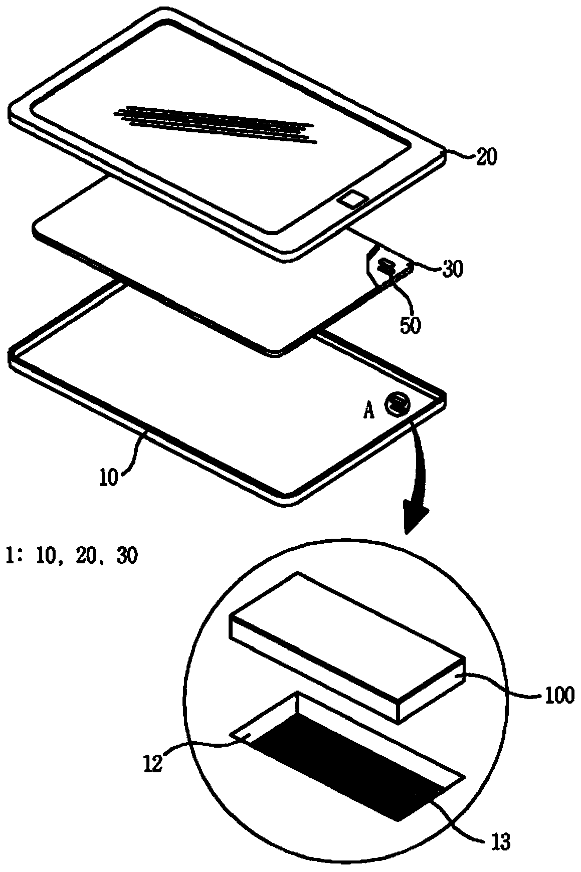
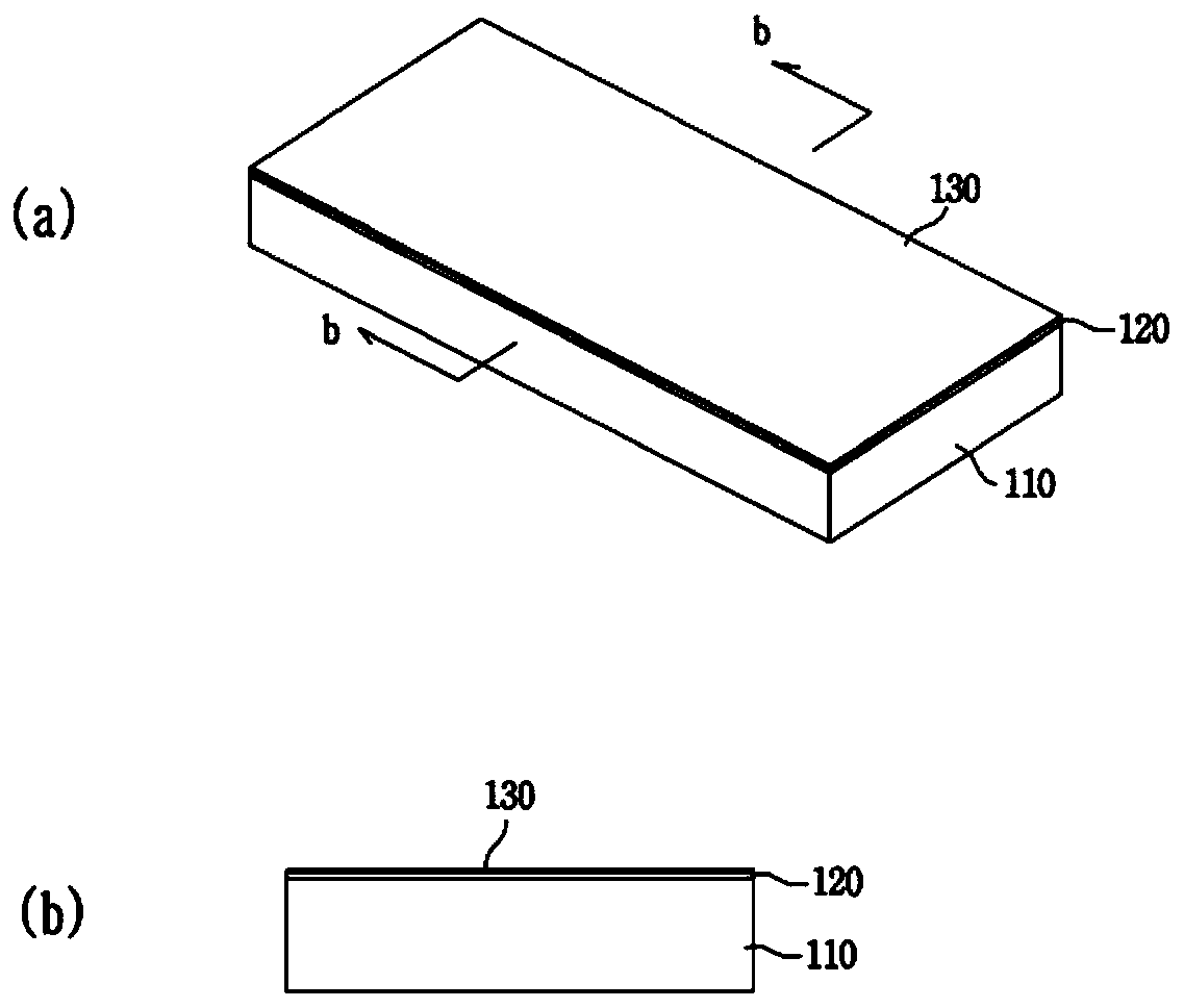
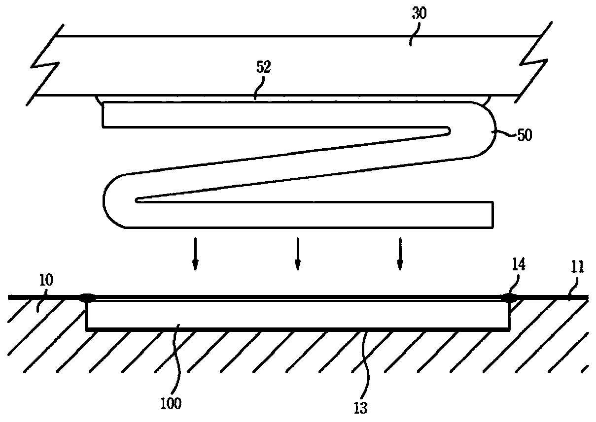
Mounting structure for electric contact terminal
A technology for electrical contact terminals and installation structures, which is applied in the direction of contact parts, conductive adhesive connections, parts of connection devices, etc., and can solve the problem of increased shell surface resistance, increased resistance, and low mechanical strength of the metal shell surface, etc. problem, to achieve the effect of low material cost, easy mechanical friction, and omission of welding steps
- Summary
- Abstract
- Description
- Claims
- Application Information
AI Technical Summary
Problems solved by technology
Method used
Image

Examples
Embodiment Construction
[0040] It should be noted that the technical terms used in the present invention are only used to describe specific embodiments, and are not intended to limit the present invention. In addition, unless the technical terms used in the present invention are specifically defined as other meanings in the present invention, they should be interpreted as meanings that can be generally understood by those with basic knowledge in the technical field to which the present invention pertains, and should not be interpreted as overly encompassing meanings or overly narrowed meanings. Furthermore, when the technical terms used in the present invention are erroneous technical terms that cannot accurately express the idea of the present invention, they should be replaced with technical terms that can be correctly understood by those skilled in the art.
[0041] Hereinafter, specific embodiments of the present invention will be described in detail with reference to the drawings.
[0042] f...
PUM
 Abstract
Description
Claims
Application Information