
Novel hub power device and electric bicycle

A power unit and wheel hub technology, which is applied to wheel transmissions, electromechanical devices, electric components, etc., can solve the problems of small output torque, large volume, and difficult climbing, and achieve large transmission ratio, small structural volume, and safety factor. high effect

Pending Publication Date: 2019-07-19
M& SE DRIVING SYST CO LTD
View PDF0 Cites 2 Cited by
  • Summary
  • Abstract
  • Description
  • Claims
  • Application Information

AI Technical Summary

Problems solved by technology

[0003] At present, the wheel hub power devices of electric bicycles on the market are mainly divided into two categories, direct drive power devices and traditional toothed power devices; wherein, the disadvantages of the direct drive power devices are large volume, small output torque, and difficult climbing. Large loads are easy to burn out; although the torque of the traditional toothed power unit has been improved compared with the direct drive motor, the volume is still large and affects the appearance
Moreover, in order to achieve a larger transmission ratio of gear transmission, the existing power unit (motor) generally uses a broken shaft design. The broken shaft design refers to dividing the central shaft into three sections, which are used to make the sun gear smaller, thereby increasing Transmission ratio; but this structure will lead to weakening of the strength of the entire mandrel; traditional power devices also use a fixed shaft hollow outlet, that is, a through hole is opened in the middle of the fixed shaft to lead the outlet end, which will also weaken the strength of the mandrel
Therefore, the existing hub power device will greatly reduce the overall working reliability and safety of the electric bicycle

Method used


Image

  • Novel hub power device and electric bicycle
  • Novel hub power device and electric bicycle
  • Novel hub power device and electric bicycle

Examples


Embodiment

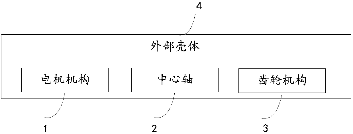
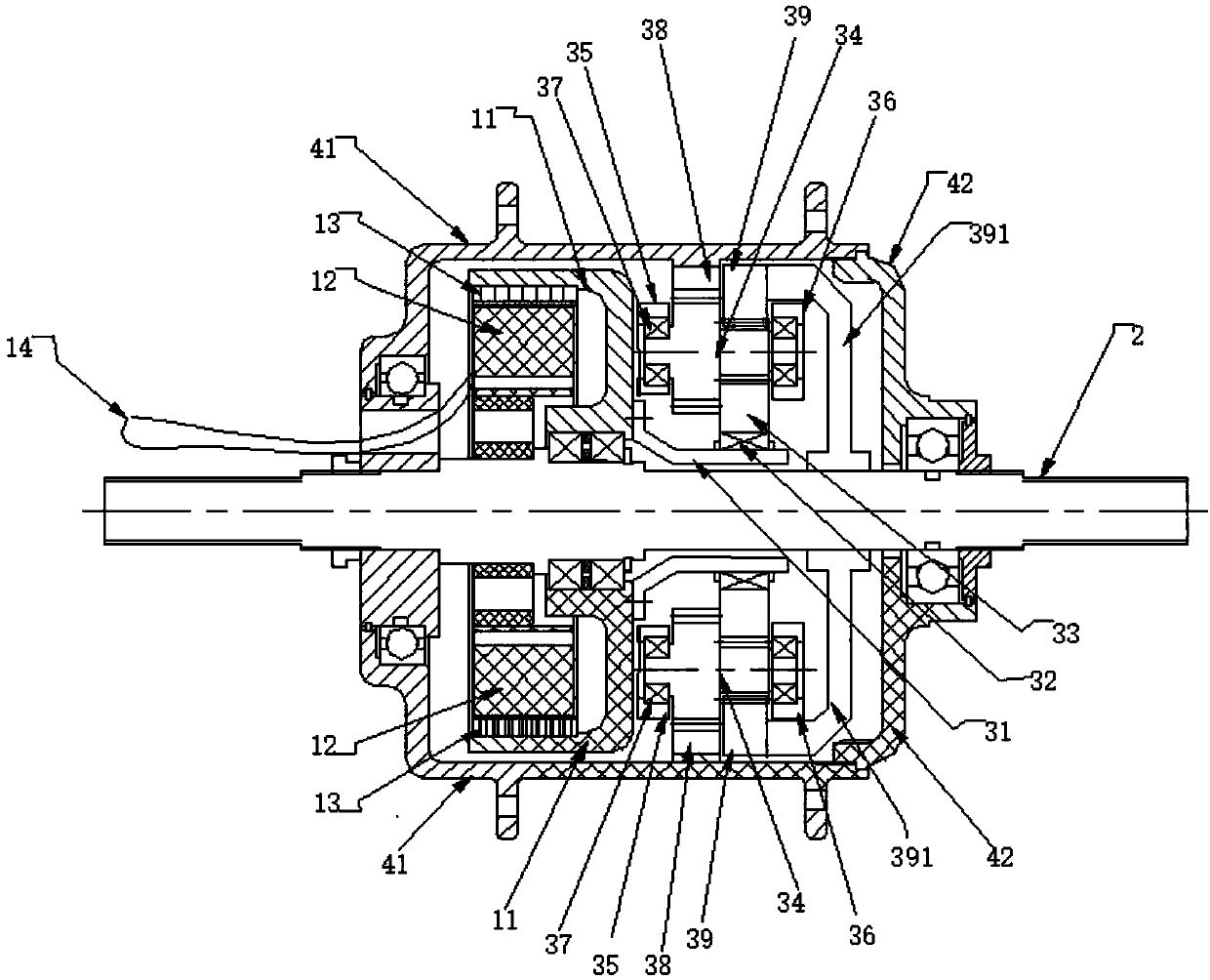
[0037] This embodiment proposes a novel hub power device, such as figure 1 As shown, the device includes a motor mechanism 1, a central shaft 2, a gear mechanism 3 and an external housing 4; specifically, as figure 2 As shown, the motor mechanism 1, the central shaft 2, and the gear mechanism 3 are all located in the outer casing 4, and the central shaft 2 is a fixed shaft, and the motor mechanism 1 and the gear mechanism 3 are sleeved on the outer casing 4. on the central axis 2;

[0038] Such as figure 2As shown, the gear mechanism 3 includes a hollow shaft sleeve 31, a one-way clutch 32, a sun gear 33, and a double planetary gear 34 that are arranged outwardly on the central shaft 2 in sequence; and one end of the hollow shaft sleeve 31 It is fixedly connected with the motor mechanism 1, and the other end of the hollow shaft sleeve 31 is in interference fit with the inner ring of the one-way clutch 32; the outer ring of the one-way clutch 32 is in contact with the inner...


PUM


Abstract

The invention discloses a novel hub power device and an electric bicycle. The novel hub power device comprises a motor mechanism, a central shaft, a gear mechanism and an outer shell; the gear mechanism comprises a hollow shaft sleeve, a one-way clutch, a sun gear and a duplex planetary gear which are sequentially arranged on the central shaft outwards in a sleeving mode; the gear mechanism further comprises a planet carrier assembly and a gear ring assembly; the planet carrier assembly comprises a left planet carrier and a right planet carrier which are fixedly connected; the gear ring assembly comprises a left gear ring and a right gear ring, and the left gear ring and the right gear ring are meshed with the duplex planetary gear in the middle of the outer side of the duplex planetary gear; the left gear ring is fixed to the outer shell, and the right gear ring is connected with the central shaft through an auxiliary piece. The power device has a small structural size and can achievea larger transmission ratio; and the central shaft is of a whole-shaft structure, so that the strength of the central shaft (fixed shaft) cannot be reduced, and the safety coefficient is high.

Description

technical field [0001] The invention relates to the technical field of motors, in particular to a novel hub power device and an electric bicycle. Background technique [0002] In recent years, electric bicycles have gradually been accepted by consumers as an environmentally friendly and energy-saving means of transportation. Whether at home or abroad, the sales of electric bicycles in the world are also increasing year by year, and the trend of electric bicycles replacing bicycles is gradually expanding. , and the electric bicycle hub power unit is the core component of the electric bicycle, and its quality often determines the overall quality of the electric bicycle. [0003] At present, the wheel hub power devices of electric bicycles on the market are mainly divided into two categories, direct drive power devices and traditional toothed power devices; wherein, the disadvantages of the direct drive power devices are large volume, small output torque, and difficult climbing...

Claims


Application Information

Patent Timeline
IPC IPC(8): B62M6/65B62M11/00H02K7/116
CPCB62M6/65B62M11/00H02K7/116
Inventor 鲁宇波吴聪宋文权徐浩杰
Owner M& SE DRIVING SYST CO LTD
Learn More