
Lifting mechanism, lifting platform device, photoetching machine and photoetching method

A lifting mechanism and limit mechanism technology, applied in the field of lifting table device and lifting mechanism, can solve the problems of far distance, the lifting table system can not meet the demand difference, and the lifting table system cannot be manufactured, so as to improve the lithography effect and high efficiency and reliability, the overall structure is simple and reliable

Inactive Publication Date: 2019-07-19
SHANGHAI MICRO ELECTRONICS EQUIP (GRP) CO LTD
View PDF6 Cites 4 Cited by
  • Summary
  • Abstract
  • Description
  • Claims
  • Application Information

AI Technical Summary

Problems solved by technology

At present, all the lifting table systems found on the market cannot meet the needs and are far from each other
And, the inventor consulted a number of well-known lifting platform manufacturing companies that can provide customized lifting platform services, and was told that it is impossible to manufacture a suitable lifting platform system that satisfies the working conditions of high precision, large load and small size at the same time

Method used


Image

  • Lifting mechanism, lifting platform device, photoetching machine and photoetching method
  • Lifting mechanism, lifting platform device, photoetching machine and photoetching method
  • Lifting mechanism, lifting platform device, photoetching machine and photoetching method

Examples


Embodiment 1

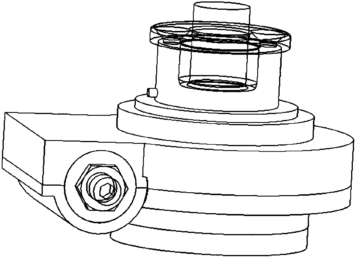
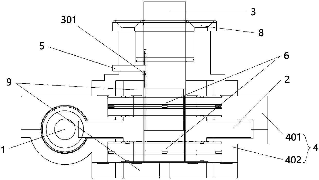
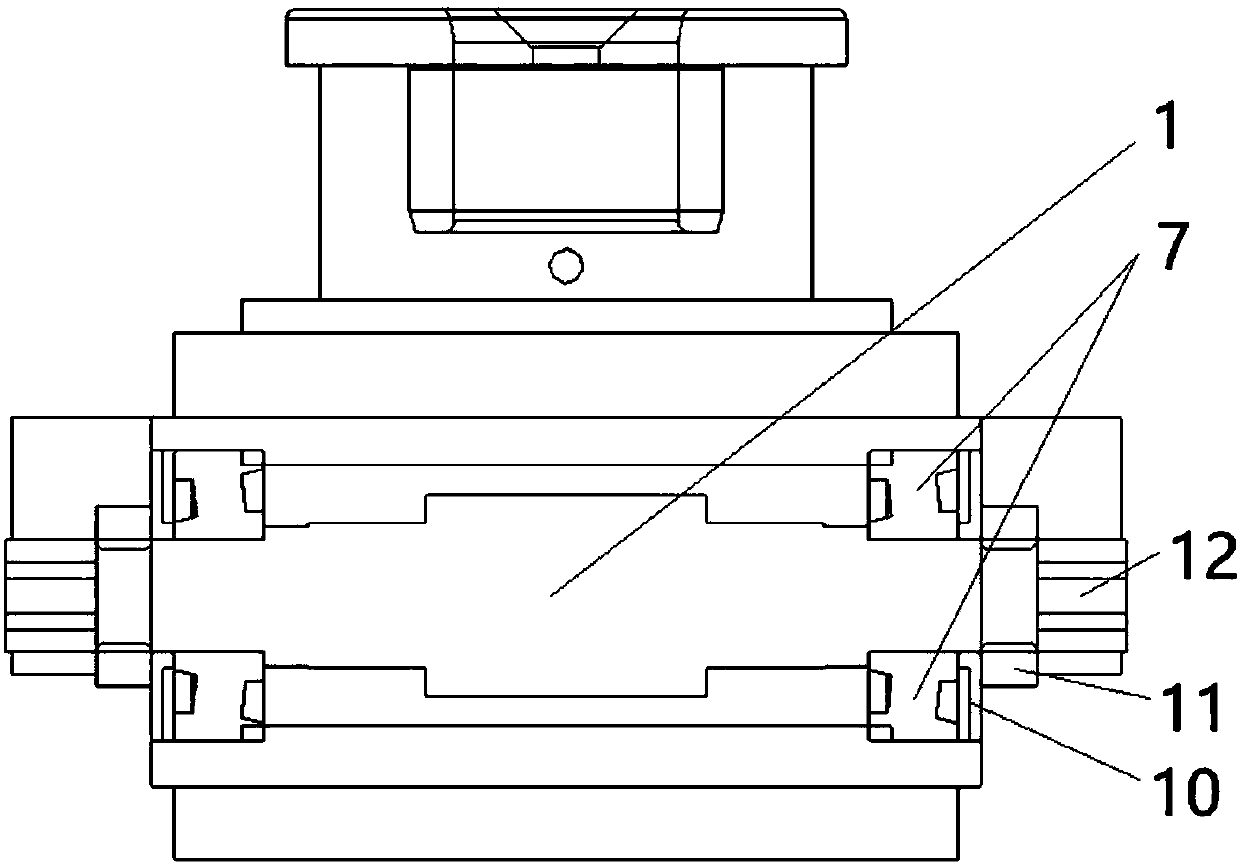
[0037] first, figure 1 The overall structural diagram of the lifting mechanism in Embodiment 1 of the present invention, figure 2 It is a structural schematic diagram of the transmission mechanism in Embodiment 1 of the present invention, image 3 and Figure 4 It is a cross-sectional view of the lifting mechanism in Embodiment 1 of the present invention, and it is referred to below Figure 1 to Figure 4 As shown, a lifting mechanism is provided in this embodiment, and the lifting mechanism includes a box 4, a worm 1, a worm wheel 2 and a screw 3; the worm 1 and the worm wheel 2 are arranged in the box 4 , the worm 1 is mated with the external thread of the worm wheel 2, the internal thread of the worm wheel 2 is sleeved on the screw 3, and the screw 3 is vertically arranged and extends from the box 4 ; When the worm 1 rotates, the worm wheel 2 is driven to rotate, and the screw 3 is driven to move up and down in the vertical direction through the rotation of the worm whee...


PUM

PropertyMeasurementUnit
distanceaaaaaaaaaa

Abstract

The invention provides a lifting mechanism, a lifting platform device, a photoetching machine and a photoetching method. The lifting mechanism comprises a box body, a worm, a worm gear and a screw rod, wherein the worm gear is driven to rotate when the worm rotates, and the screw rod is driven to ascend and descend in the vertical direction through the rotation of the worm gear. The lifting mechanism can meet the vertical lifting adjustment requirements of high precision and large load at the same time in a limited space. In addition, an anti-rotation limiting mechanism is further adopted in the lifting mechanism, so that the screw rod is prevented from rotating, then the output of the worm gear and the worm can be completely received by the screw rod, meanwhile, the movement range of thescrew rod is limited, and then a whole transmission mechanism has higher efficiency and reliability. In addition, the lifting mechanism makes up the vacancy of high-precision, large-load and small-size lifting mechanisms in the prior art, is applied to the fields such as the photoetching machine and can also correspondingly improve the photoetching effect of the photoetching machine.

Description

technical field [0001] The invention relates to a lifting mechanism, in particular to a lifting mechanism, a lifting platform device, a photolithography machine and a photolithography method. Background technique [0002] The lifting mechanism is a common mechanism that can be used to lift people or goods to a certain height and can be used in many fields. For example, in the field of semiconductor manufacturing, the lifting mechanism is applied to the workpiece table of the lithography machine. The base frame of the workpiece table can be used to support and adjust the entire magnetic levitation table module. [0003] However, due to the size limitation of the front-end lithography machine, the installation position and space of the lifting mechanism are very limited. Under this premise, the requirements for its adjustment accuracy, stability and reliability are also very high. At the same time, it is also required that the lifting mechanism can withstand a large load of, ...

Claims


Application Information

Patent Timeline
Patent Type & Authority Applications(China)
IPC IPC(8): B66F3/18B66F7/14G03F7/20
CPCB66F3/18B66F7/14G03F7/70716G03F7/70758B23K26/10F16H55/24G03F7/20
Inventor 管博然黄亚庆丛国栋
Owner SHANGHAI MICRO ELECTRONICS EQUIP (GRP) CO LTD
Learn More