Special tool for heat treatment of shield hob ring and machining process thereof

A processing technology and a technology of a knife ring, applied in the field of tooling and its processing technology, can solve the problems of uneven heating of the knife ring, uneven hardness, low furnace loading, etc., and achieve the effect of ensuring uniform heating and simple and reasonable structure.

Pending Publication Date: 2019-07-19
中铁工程装备集团隧道设备制造有限公司
View PDF0 Cites 0 Cited by
  • Summary
  • Abstract
  • Description
  • Claims
  • Application Information

AI Technical Summary

Problems solved by technology

Therefore, it is urgent to design a heat treatment tooling suitable for shield hob cutter rings, so as to avoid problems such as uneven heating, uneven hardness, and low furnace charging capacity of the cutter rings, and to ensure the safety and efficiency of the heat treatment process of the hob cutter rings. , The quality of the knife ring does not decrease during batch heat treatment

Method used


Image

  • Special tool for heat treatment of shield hob ring and machining process thereof
  • Special tool for heat treatment of shield hob ring and machining process thereof
  • Special tool for heat treatment of shield hob ring and machining process thereof

Examples


Embodiment 1

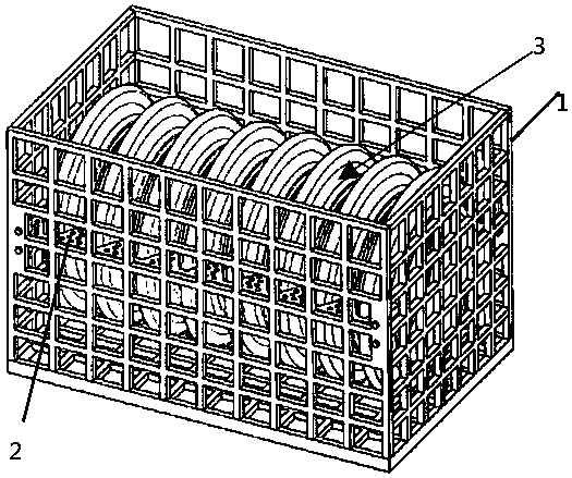
[0017] A special tooling for heat treatment of a shield hob cutter ring, which includes a housing 1, a hob cutter ring fixing frame 2 is installed at the bottom of the housing, and hob cutter ring fixing frames are respectively installed on both sides inside the housing 2;

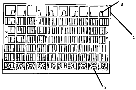
[0018] The housing 1 described in this embodiment is a rectangular frame body, and ribs are arranged at intervals perpendicular to each other on the bottom surface and the vertical surface of the housing, and the two short beams on the bottom surface of the housing and the middle of the four long vertical columns on the vertical surface are provided with round holes for assembly. rectangular plate;

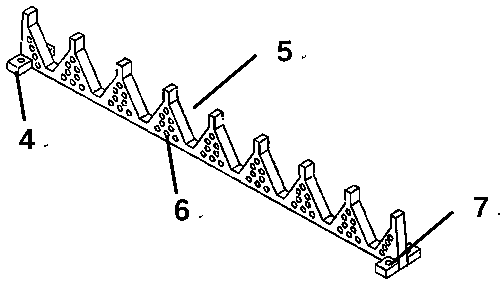
[0019] The hob cutter ring fixing frame 2 described in this embodiment is evenly distributed with grooves 5 matching the outer dimensions of the hob cutter ring, and fixing seats 4 are respectively provided at both ends of the shelf, and screw holes are opened on the fixing seats 7. The screw holes correspond...

Embodiment 2

[0025] The casing 1 and the hob cutter ring fixing frame 2 described in Embodiment 1 are all cast and formed by high temperature resistant nickel-based alloy.

[0026] The composition of its nickel-based alloy: C: 0.10%, Si: 1.00%, Mn: 1.00%, Cr: 18%, Ni: 48%, Al: 5%, S: 0.019%, P: 0.024%, the rest Fe .

Embodiment 3

[0028] The casing 1 and the hob cutter ring fixing frame 2 described in Embodiment 1 are all cast and formed by high temperature resistant nickel-based alloy.

[0029] The composition of its nickel-based alloy: C: 0.15%, Si: 0.8%, Mn: 0.8%, Cr: 16%, Ni: 45%, Al: 3%, S: 0.018%, P: 0.023%, the rest Fe .


PUM


Abstract

The invention provides a special tool for heat treatment of a shield hob ring. The tool comprises a basket body, a hob cutter ring fixing frame is arranged at the bottom of the basket body, and hob cutter ring fixing frames are arranged on the two sides inside the basket body respectively; the hob cutter ring fixing frame is uniformly formed in grooves matched with the outer size of the hob cutterring, fixing seats are arranged at the two ends of the rack respectively, screw holes are formed in the fixing seats, and a plurality of through holes are uniformly formed in the rack. The basket body and the hob ring fixing frame are formed by casting high-temperature-resistant nickel-based alloys in a casting mode, long-term service under high-temperature environment of 1000 DEG C-1200 DEG C, and can bear high-temperature long-term service under the quenching process of 1100 DEG C and can be repeatedly subjected to thermal shock; and the requirements of the heat treatment process of the cutter ring can be met. The heating uniformity of the cutter ring heat treatment process and the uniformity of the cutter ring hardness can be guaranteed to the maximum degree, and the hob cutter ring fixing frames with different sizes can be replaced conveniently so as to meet the use of hob cutter rings with different sizes.

Description

technical field [0001] The invention relates to a shield hob cutter ring, in particular to a special tooling suitable for heat treatment of a shield hob cutter ring and its processing technology. Background technique [0002] As an efficient, safe, economical and green tunnel excavation equipment, shield tunnel boring machine is widely used in tunnel construction such as water diversion, urban subway, highway and railway. The hob cutter ring is a key part of the shield machine that directly breaks rocks. Heat treatment is a key process to ensure the good mechanical properties of the cutter ring, which directly affects the efficiency and cost of tunnel construction. Therefore, it is urgent to design a heat treatment tooling suitable for shield hob cutter rings, so as to avoid problems such as uneven heating, uneven hardness, and low furnace charging capacity of the cutter rings, and to ensure the safety and efficiency of the heat treatment process of the hob cutter rings. , ...

Claims


Application Information

Patent Timeline
IPC IPC(8): C21D9/22C22F1/10C22F1/00C22C19/05C22C30/00
CPCC21D9/22C22F1/10C22F1/00C22C19/05C22C30/00
Inventor 郭浩王笠尚勇李胜永芦海俊李英发
Owner 中铁工程装备集团隧道设备制造有限公司
Why Eureka
Try Eureka