
A hollow aluminum-injected steel claw for an aluminum electrolytic anode

A technology of aluminum electrolytic anode and empty steel claw is applied in the field of electrolytic aluminum anode steel claw, which can solve the problems of large current empty consumption, high resistivity and high production cost, and achieve the effects of reducing electrical loss, high mechanical strength and reducing production cost.

Active Publication Date: 2020-11-10
贵州铝城铝业原材料研究发展有限公司
View PDF1 Cites 0 Cited by
  • Summary
  • Abstract
  • Description
  • Claims
  • Application Information

AI Technical Summary

Problems solved by technology

[0004] To sum up, the prior art has the technical problems of high resistivity of the body of the entire electrolytic aluminum anode steel claw guide rod assembly, excessive current idle consumption, and high production cost.

Method used


Image

  • A hollow aluminum-injected steel claw for an aluminum electrolytic anode

Examples


Embodiment Construction

[0019] The present invention will be further described below in conjunction with the accompanying drawings and embodiments, but not as a basis for limiting the present invention.

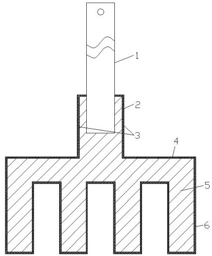
[0020] Example. A hollow aluminum-injected steel claw for an aluminum electrolytic anode, which is composed of figure 1 As shown, it includes a hollow steel claw steel shell 2, the upper end of the hollow steel claw steel shell 2 is provided with an aluminum guide rod connecting plug 3, the lower end of the hollow steel claw steel shell 2 is provided with a steel claw beam 4, and the lower end of the steel claw beam 4 is provided with a set of The steel claw foot 6, the steel claw beam 4 and the steel claw foot 6 are hollow structures, and the aluminum guide rod connection plug 3 on the hollow steel claw steel shell 2, the steel claw beam 4 and the steel claw foot 6 are filled with an aluminum core 5.

[0021] An aluminum guide rod 1 is arranged inside the aluminum guide rod connection plug 3 on th...


PUM


Abstract

The invention discloses an aluminum electrolysis anode hollow aluminum pouring steel claw. A hollow steel claw steel shell is included. An aluminum guide rod connecting plug is arranged at the upper end of the hollow steel claw steel shell. A steel claw beam is arranged at the lower end of the hollow steel claw steel shell. A set of steel claw feet are arranged at the lower end of the steel claw beam. The steel claw beam and the steel claw feet are each of a hollow structure. An aluminum core is poured into the aluminum guide rod connecting plug on the hollow steel claw steel shell, the steelclaw beam and the steel claw feet. By means of the aluminum electrolysis anode hollow aluminum pouring steel claw, the electrical resistivity of an anode guide rod and the steel claw is reduced, electrical losses are reduced, the production cost is reduced, and the beneficial effect that the integral mechanical strength is high is achieved.

Description

technical field [0001] The invention relates to the technical field of electrolytic aluminum anode steel claws, in particular to the hollow aluminum-injected steel claws of aluminum electrolytic anodes. Background technique [0002] In the existing prebaked anode electrolytic aluminum production, the anode steel claws and the anode carbon blocks are all connected by casting of phosphorus pig iron, and there are 2 to 4 diameters of 160 to 180 mm on the upper surface of the prebaked anode carbon block in the conductive direction, and the depth It is a circular groove of 80-110mm, commonly known as a carbon bowl. When the anode is assembled, the carbon bowl is used to place the anode claw head. The anode claw head is cast in the carbon bowl with phosphorus pig iron, and the steel claw head and the aluminum conductive rod are exploded through the aluminum steel. In this way, the anode conductive rod and the anode carbon block are connected together to form an anode carbon block ...

Claims


Application Information

Patent Timeline
Patent Type & Authority Patents(China)
IPC IPC(8): C25C3/12B22D19/16
CPCB22D19/16C25C3/125
Inventor 邹铜华邹建明
Owner 贵州铝城铝业原材料研究发展有限公司
Learn More