Spar cap, wind turbine blade, method for fabrication of both

一种风力涡轮机、翼梁帽的技术,应用在翼梁帽领域,能够解决难以实现、小容差修复昂贵等问题,达到整体电阻减小、大制造和定位误差的效果

Active Publication Date: 2019-07-19
SIEMENS GAMESA RENEWABLE ENERGY AS
View PDF5 Cites 3 Cited by
  • Summary
  • Abstract
  • Description
  • Claims
  • Application Information

AI Technical Summary

Problems solved by technology

Small tolerances are difficult to achieve especially for larger structures and where failures are difficult to detect and expensive to repair

Method used


Image

  • Spar cap, wind turbine blade, method for fabrication of both
  • Spar cap, wind turbine blade, method for fabrication of both
  • Spar cap, wind turbine blade, method for fabrication of both

Examples


Embodiment Construction

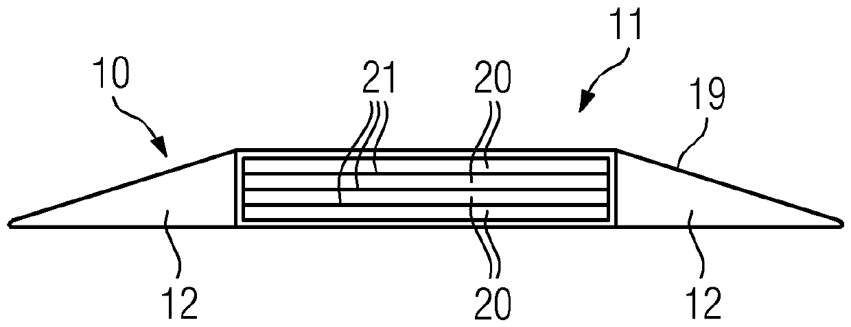
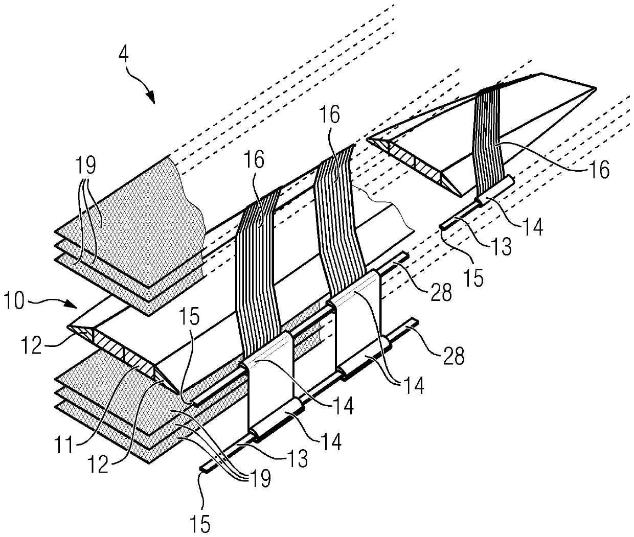
[0052] exist figure 1 , a schematic diagram of a wind turbine 1 is shown. A wind turbine 1 comprises a hub 2 with a rotor comprising a plurality of wind turbine blades 3 attached to the hub 2 . Each wind turbine blade 3 comprises at least one spar cap 4, wherein the position of the spar cap 4 in or in the wind turbine rotor blade 3 is shown by dashed lines. The spar caps 4 serve to increase the mechanical stability of the wind turbine blade 3 during operation of the wind turbine 1, in particular along the longitudinal axis of the spar cap 4 or the longitudinal axis of the wind turbine blade 3, respectively.

[0053] exist figure 2 , a cross section through a wind turbine blade 3 is shown. The wind turbine blade 3 comprises two spar caps 4 arranged substantially perpendicularly to a web structure 5 arranged in an inner cavity 6 of the wind turbine blade 3 . The wind turbine blade 3 also comprises a panel 7 forming the leading edge of the wind turbine blade 3 , and two pane...


PUM


Abstract

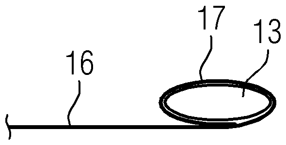
The invention relates to a spar cap, a wind turbine blade, and a method for fabrication of both. A spar cap for a wind turbine blade (3), comprising a main body (10), which comprises an electrically conductive portion (11), and at least one metal conductor (13, 28), wherein the metal conductor (13) comprises a terminal portion (15, 26) and at least one connection portion (14), wherein the connection portion (14) of the metal conductor (13) is wrapped by a first end (17) of an electrically conductive and stripe-shaped carbon fibre mat (16), which abuts with a second end (18) at least partly onthe electrically conductive portion (11) of the main body (10).

Description

technical field [0001] The invention relates to a spar cap for a wind turbine blade comprising a main body comprising an electrically conductive part and at least one metallic conductor, wherein the metallic conductor comprises a terminal part and at least one connecting part. Furthermore, the invention relates to a wind turbine, a method for manufacturing a spar cap and a method for manufacturing a wind turbine blade. Background technique [0002] The size of wind turbines and their rotor blades is increasing exponentially. The ever increasing size of rotor blades or wind turbine blades requires special designs of wind turbine blades in order to maintain and ensure their mechanical stability and integrity during operation of the wind turbine. Materials suitable for the design of large turbine blades are, for example, fiber-based composite materials, such as fiber-reinforced plastics, due to their high stiffness-to-weight ratio. An important component for the mechanical st...

Claims


Application Information

Patent Timeline
Patent Type & Authority Applications(China)
IPC IPC(8): F03D1/06F03D80/30B29D99/00
CPCF03D1/0675F03D80/30B29D99/0025F05B2280/6003F05B2230/60Y02E10/72Y02P70/50B29K2307/04
Inventor D.吉罗拉莫
Owner SIEMENS GAMESA RENEWABLE ENERGY AS
Why Eureka
Try Eureka