
A sensor layout method for air conditioning system test

A technology of air-conditioning system and layout method, which is applied to the testing of instruments, measuring devices, machines/structural components, etc., and can solve problems such as misjudgment of system capabilities, insufficient sensor layout locations, and increased analysis costs

Active Publication Date: 2021-04-27
WUHAN GROVE HYDROGEN AUTOMOBILE CO LTD
View PDF5 Cites 0 Cited by
  • Summary
  • Abstract
  • Description
  • Claims
  • Application Information

AI Technical Summary

Problems solved by technology

[0004] Aiming at the deficiencies of the prior art, the present invention provides a sensor arrangement method for air conditioning system test, which solves the problem that the sensor arrangement position proposed in the above-mentioned background technology is not comprehensive enough, which indirectly leads to icing on the surface of the evaporator, large temperature difference at the air outlet and errors. Judgment of system capabilities, and increased analysis costs, can not meet people's needs and other issues

Method used


Image

  • A sensor layout method for air conditioning system test

Examples


Embodiment Construction

[0015] The following will clearly and completely describe the technical solutions in the embodiments of the present invention with reference to the accompanying drawings in the embodiments of the present invention. Obviously, the described embodiments are only some, not all, embodiments of the present invention.

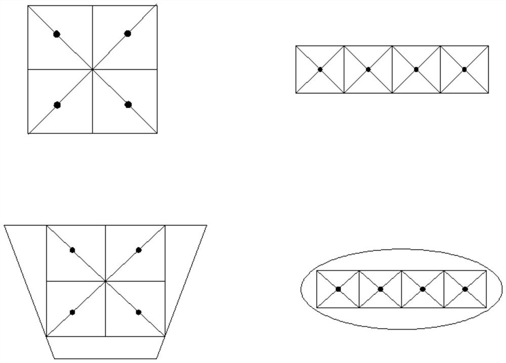
[0016] see figure 1 , the present invention provides a technical solution: a method for arranging sensors for air-conditioning system tests. Warm air core, condenser temperature sensor, air-conditioning pipe temperature and pressure sensor, system flow, system oil content, head temperature sensor, foot temperature sensor, vehicle air outlet and outside environment temperature;

[0017] The pressure limit of the temperature and pressure sensor of the air-conditioning pipe is: low pressure - 0 ~ 15bar; high pressure - 0 ~ 35bar, and the temperature and pressure sensor of the air-conditioning pipe includes the inlet and outlet of the compressor, the inlet and outlet of ...


PUM


Abstract

The invention discloses a sensor layout method for an air conditioning system test, relates to the technical field of air conditioning systems, and specifically relates to a sensor layout method for an air conditioning system test. Arrangement principle of tuyere and thermocouple, evaporator temperature sensor, warm air core, condenser temperature sensor, air conditioning pipe temperature and pressure sensor, system flow, system oil content, head temperature sensor, foot temperature sensor, vehicle air outlet and the ambient temperature outside the vehicle. The air-conditioning system test sensor arrangement method can effectively avoid the occurrence of icing on the evaporator surface. If the evaporator surface temperature sensor is not arranged properly, it will not be possible to accurately understand the temperature distribution of the evaporator surface under different working conditions, thereby affecting The arrangement of the evaporator temperature sensor, and the arrangement method, can minimize or eliminate the risk of icing during system operation.

Description

technical field [0001] The invention relates to the technical field of air-conditioning systems, in particular to a method for arranging sensors for air-conditioning system tests. Background technique [0002] The sensors of the automatic air conditioning control system generally include the temperature sensor inside the cabin, the temperature sensor outside the cabin, the evaporator temperature sensor, the solar sensor, the water temperature sensor, etc., among which the water temperature sensor is located at the engine water outlet, and it will feed back the cooling water temperature to the ECU. When the temperature is high, the ECU can disconnect the compressor clutch to protect the engine. At the same time, the ECU can control the valve of the cooling water leading to the heating core according to the water temperature. Each sensor will feed back the temperature information to the ECU. Control the temperature of the air flow, for example, when the temperature is too low,...

Claims


Application Information

Patent Timeline
Patent Type & Authority Patents(China)
IPC IPC(8): G01M99/00
CPCG01M99/005G01M99/008
Inventor 魏成龙郝义国陈振武
Owner WUHAN GROVE HYDROGEN AUTOMOBILE CO LTD
Learn More