Cooling structure of bearing unit

A technology of cooling structure and bearing device, which is applied in the direction of bearing cooling, bearing assembly, bearing, etc.

Active Publication Date: 2021-03-09
NTN CORP
View PDF11 Cites 0 Cited by
  • Summary
  • Abstract
  • Description
  • Claims
  • Application Information

AI Technical Summary

Problems solved by technology

[0005] The rise in the temperature of the heat-generating bearing is the result of an increase in preload, and it is planned to suppress it as much as possible in consideration of the increase in speed and precision of the spindle.

Method used


Image

  • Cooling structure of bearing unit
  • Cooling structure of bearing unit
  • Cooling structure of bearing unit

Examples


Embodiment Construction

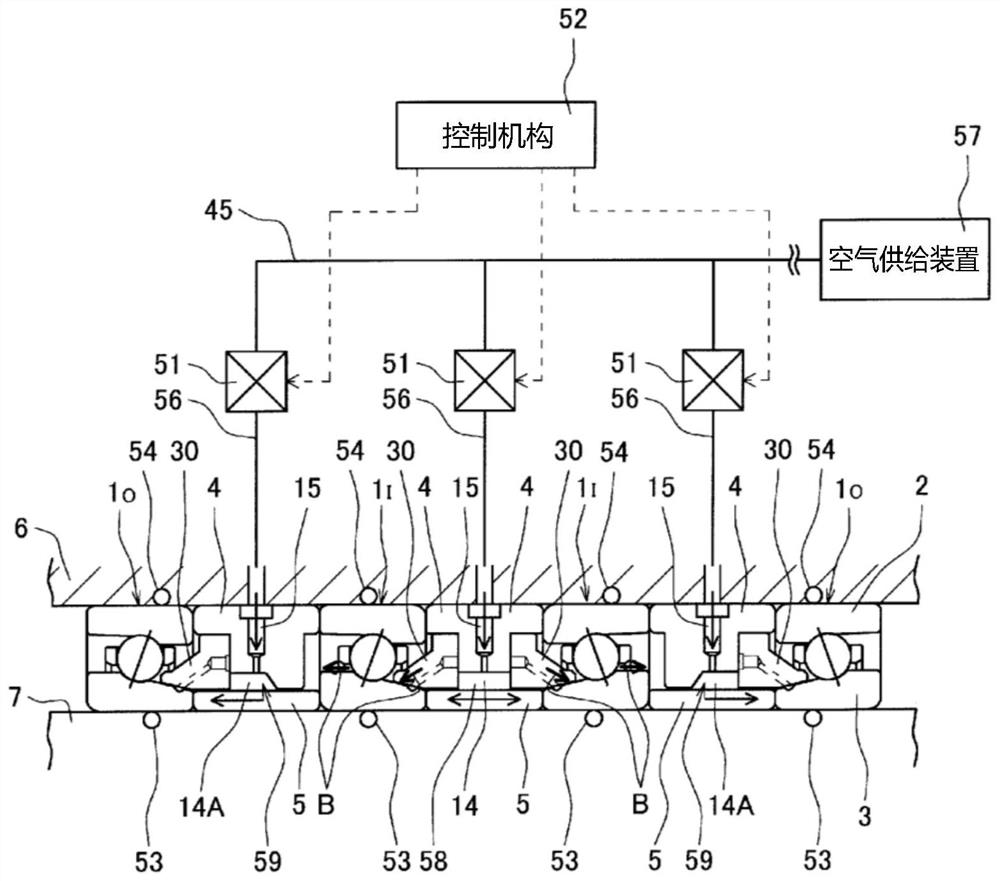
[0049] according to Figure 1 to Figure 8 , the first embodiment of the present invention will be described. picture figure 1 As shown, in the cooling structure of the bearing device J, the outer surfaces of the adjacent rolling bearings 1, 1 in the arrangement of the rolling bearings 1 arranged in three or more rows (in the illustrated example, four rows) in the axial direction are An outer ring spacer 4 and an inner ring spacer 5 are interposed between the rings 2, 2 and between the inner rings 3, 3, respectively. The outer ring 2 and the outer ring spacer 4 are provided on the inner periphery of the housing 6 , and the inner ring 3 and the inner ring spacer 5 are fitted on the outer periphery of the main shaft 7 as the rotation axis.

[0050] An air nozzle 15 is arranged on the above-mentioned outer ring spacer 4 , and the air nozzle 15 sprays compressed air to the inner ring spacer 5 opposite to each other. In addition, a valve body 51 is arranged, which adjusts the corr...


PUM


Abstract

The cooling structure of the bearing device of the present invention includes, among the plurality of outer ring spacers (4), an air nozzle (15) that sprays compressed air toward the facing inner ring spacer (5); a valve body (51) that Adjustment of compressed air sprayed from corresponding nozzles of these air nozzles (15); control mechanism (52); temperature detection mechanism (53, 54), which measures the temperature of each rolling bearing (1). The control mechanism (52) controls the valve body (51) in the following manner: using measured values ​​of temperatures measured by a plurality of temperature measurement mechanisms (53, 54), selected according to established rules The air nozzle (15) sprays compressed air.

Description

[0001] related application [0002] This application claims the priority of the application dated November 10, 2016 and the application number is JP Japanese Patent Application No. 2016-219512, and by referring to the entirety, this is incorporated as a content constituting a part of this application. technical field [0003] The present invention relates to a cooling structure of a bearing device, such as a main shaft of a machine tool and a cooling structure of a bearing assembled on the main shaft. Background technique [0004] In the spindle device of a machine tool, in order to ensure machining accuracy, it is necessary to suppress the temperature rise of the device to a small degree. However, in recent machine tools, the speed tends to be increased in order to improve machining efficiency, and the speed of heat generation from the bearings supporting the main shaft is accelerated, and the amount of heat generated is increased. Furthermore, the number of built-in motor...

Claims


Application Information

Patent Timeline
Patent Type & Authority Patents(China)
IPC IPC(8): F16C37/00F16C19/18F16C41/00
CPCF16C41/00F16C33/6659F16C37/007F16C2233/00F16C2322/39F16C19/546F16C35/12F16C19/184B23Q11/123F16C19/525B23Q17/0985F16C41/007F16C33/667F16C33/58F16C19/18B23Q11/12B23Q17/00
Inventor 那须惠介
Owner NTN CORP
Why Eureka
Try Eureka