Method and device for soldering tin by induction heating of magnetism collecting rod

A technology of induction heating and magnetic collection, applied in welding equipment, metal processing, metal processing equipment, etc., can solve the problems of frequent replacement of soldering iron tips, increased production costs, limited use of occasions, etc., and achieves short welding time for a single point and saves production. The effect of improving cost and production efficiency

Pending Publication Date: 2019-07-23
深圳市双建科技有限公司
View PDF10 Cites 4 Cited by
  • Summary
  • Abstract
  • Description
  • Claims
  • Application Information

AI Technical Summary

Problems solved by technology

[0005] (3) Since the power of traditional soldering irons is generally between tens of watts and hundreds of watts, when welding some relatively large soldering points, the heating time is relatively long and the efficiency is low;
[0006] (4) Since the soldering iron tip will be gradually damaged during use and needs to be replaced, when the production volume is large, the replacement of the soldering iron tip is frequent, thereby increasing the production cost
[0007] Although, the induction coil heating welding method is also used at present, but the induction magnetic field generated by the induction coil in this method is distributed 360° from the center of the induction coil, and it is easy to heat the range of the welding position accessories at the same time, so the application occasions are limited.

Method used


Image

  • Method and device for soldering tin by induction heating of magnetism collecting rod
  • Method and device for soldering tin by induction heating of magnetism collecting rod
  • Method and device for soldering tin by induction heating of magnetism collecting rod

Examples


Embodiment Construction

[0029] The structure of the present invention will be further described below in conjunction with the preferred specific embodiments of the present invention with accompanying drawings.

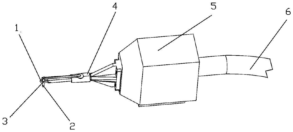
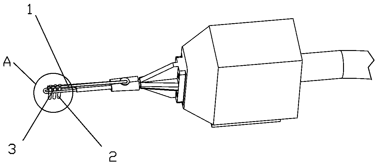
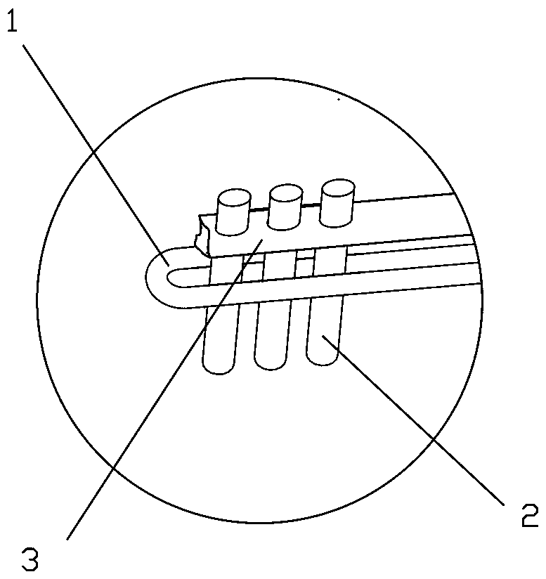
[0030] refer to Figure 1 to Figure 5 As shown in the present invention, the method of soldering with magnetic rod induction heating adopts a high-frequency power supply to provide a high-frequency working power supply for the induction coil, so that a high-frequency alternating magnetic field is generated inside the induction coil, and the magnetic rod is used to heat the inside of the induction coil. The high-frequency alternating magnetic field energy is transferred to the welding position and the soldering tin wire, and the electromagnetic principle is used to weld the heat generated by the eddy current formed by the magnetic force line on the metal surface.

[0031] In the soldering method of the present invention, when the welding operation is performed, the magnetic collecting rod 2 is...


PUM


Abstract

The invention relates to a method and device for soldering tin by induction heating of a magnetism collecting rod, and relates to the field of electronic appliances and electromechanical industries which requires a soldering technology. The defects of a conventional technology using soldering iron for soldering tin are overcome, a high-frequency power supply is adopted to provide a high-frequencyworking power supply for an induction coil to generate a high-frequency alternating magnetic field inside the induction coil, the magnetism collecting rod is used to transfer energy of the high-frequency alternating magnetic field inside the induction coil to a soldering position and a soldered tin wire, and with the adoption of an electromagnetic principle, heat energy generated by eddy current formed on the metal surface by magnetic lines is used to weld. Compared with the prior art, the method and the device have the following advantages that 1, the welding consistency is better; 2, the production efficiency is improved; 3, energy is transferred in a more concentrated manner; 4, more energy is saved; and 5, a high-frequency welding process has no consumables, but soldering with a soldering bit needs to frequently replace a soldering iron nozzle, so that the production cost is reduced more with the high-frequency welding process.

Description

technical field [0001] The invention relates to the field where the soldering process is required in the electronic appliance and electromechanical industries. Background technique [0002] For a long time, in the production and manufacturing process of electronic appliances and electromechanical industries, there has been a process that requires the use of soldering irons for soldering. However, there are inherent defects in using soldering irons for soldering. The shortcomings are mainly reflected in the following aspects: [0003] (1) Soldering iron solder is heated by heat conduction. The heat conduction process is affected by the contact area. A slight deviation in the placement angle of the soldering iron will affect the heat conduction effect, thereby affecting the quality or prolonging the welding time; [0004] (2) During use, with the gradual corrosion and damage of the soldering iron tip, the effect on heat conduction is greater, and the influence on the stability...

Claims


Application Information

Patent Timeline
Patent Type & Authority Applications(China)
IPC IPC(8): B23K1/002B23K3/00
CPCB23K1/002B23K3/00
Inventor 叶慧能陈锦昌
Owner 深圳市双建科技有限公司
Why Eureka
Try Eureka