Photovoltaic power storage distributed power generation alternating current traction power supply system and method

A traction power supply system and distributed power generation technology, applied in photovoltaic power generation, AC network circuits, AC network load balancing, etc., can solve the problems of complex composition, large scale and many equipment of traction substations

Active Publication Date: 2019-07-23
SOUTHWEST JIAOTONG UNIV
View PDF5 Cites 19 Cited by
  • Summary
  • Abstract
  • Description
  • Claims
  • Application Information

AI Technical Summary

Problems solved by technology

The existing new energy and energy storage device used in the traction power supply system is connected to the traction substation, which brings about the problem that when the remaining regenerative braking train energy is recovered through the energy storage device, the regenerative braking power flows to Traction substation, resulting in a high voltage level at the head end of the traction network, affecting the safety work of electric locomotives or EMUs running close to the traction substation
[0005] The traditional scheme of connecting distributed photovoltaic power generation and energy storage to the traction substation makes the composition of the traction substation complex and requires more equipment. The integration of photovoltaic power generation and energy storage systems makes the original traction substation larger. The footprint needs to be larger

Method used


Image

  • Photovoltaic power storage distributed power generation alternating current traction power supply system and method
  • Photovoltaic power storage distributed power generation alternating current traction power supply system and method

Examples


Embodiment 1

[0078] Embodiment 1: Traditional unilateral power supply method:

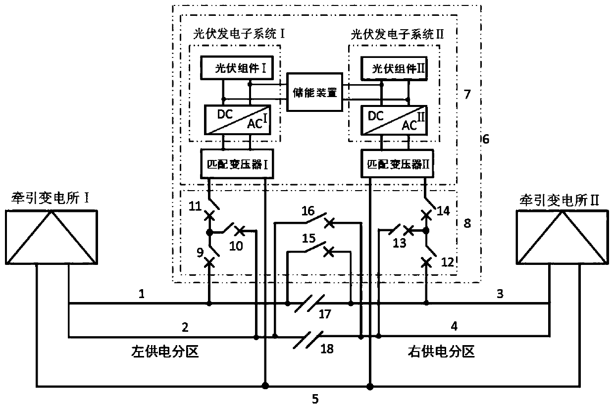
[0079] 1 Unilateral power supply mode without photovoltaic energy storage in the left power supply partition: the first circuit breaker I9 and the second circuit breaker I10 connected in parallel at the end of the left power supply partition are closed, and the uplink catenary I1 and downlink catenary I2 terminals of the left power supply partition run in parallel; The third circuit breaker Ⅰ11 is disconnected, the photovoltaic power generation sub-system I is not connected to the end of the left power supply partition, and the left power supply sub-system is supplied with electric energy by the traction substation I, working in the unilateral power supply mode without photovoltaic energy storage, the photovoltaic power generation sub-system I is overhauled Period out of operation;

[0080] 2 Unilateral power supply mode without photovoltaic energy storage in the right power supply partition: the first circuit ...

Embodiment 2

[0081] Example 2: Bilateral power supply mode of uplink and downlink parallel photovoltaic energy storage under normal operation conditions:

[0082] 3 The bilateral power supply mode of photovoltaic energy storage in parallel with uplink and downlink in the left power supply partition: the end of the left power supply partition is connected in parallel with the first circuit breaker I9 and the second circuit breaker I10 closed, the third circuit breaker I11 is closed, the uplink catenary I1 of the left power supply partition is in contact with the downlink The end of grid I2 is connected in parallel, the photovoltaic power generation sub-system I is put into the end of the left power supply partition, and the left power supply partition works in the parallel photovoltaic power generation and energy storage mode at the end of the uplink catenary I1 and the downlink I2 end, so that the left power supply partition is simultaneously powered by the traction substation I The bilater...

Embodiment 3

[0085] Embodiment three: catenary failure:

[0086] 1 Catenary failure mode:

[0087] When the uplink catenary I1 of the left power supply partition fails, the first circuit breaker I9 is ​​disconnected, and the feeder circuit breaker between the traction substation I and the uplink catenary I1 is disconnected to isolate the faulty catenary, and the non-faulty catenary still passes through The traction substation I and the photovoltaic power generation sub-system I realize single-wire bilateral power supply; when the downlink catenary I2 of the left power supply partition fails, the second circuit breaker I10 is disconnected, and the connection between the traction substation I and the downlink catenary I2 is disconnected. The feeder circuit breaker isolates the faulty catenary, and the non-faulty catenary still realizes single-line bilateral power supply through the traction substation Ⅰ and photovoltaic power generation subsystem Ⅰ;

[0088] When the uplink catenary II3 of ...


PUM


Abstract

The invention discloses a photovoltaic power storage distributed power generation alternating current traction power supply system and method. Anexistingout-phase power supply traction power supply system partition station is used foraccessing a photovoltaic power generation and storage system to the tail ends of traction networks of the left side and right side power supply partitions, bilateralpower supply is realized in each independent power supply partition through the distributed photovoltaic power generation and storage system, and double-end power source bilateral power supply of a traction power substation and a partition station photovoltaic power generation and storage systemis formed. According to the photovoltaic power storage distributed power generation alternating currenttraction power supply system and method,when the traction network is normal, the bilateral power supply of the traction power substation and the partition station photovoltaic power storage is enabledin the independent power supply partition, when the traction power substation malfunctions, cross-regional power supply by multiple power sources is realized by the adjacent traction substation and the partition station photovoltaic power storage, the voltage level of the traction network is improved, the power supply capacity is improved, and power is uninterruptedlysupplied for electric locomotives or electric motor train units; and at the same time power storage recycles locomotive regenerative feedback energy, the problem of high voltage level at the head end of the traction network caused by foldbackis avoided, and the stability and reliability of traction power supply is improved.

Description

technical field [0001] The invention belongs to the technical field of electrified railway power supply, and in particular relates to an AC traction power supply system and method for photovoltaic energy storage distributed power generation. Background technique [0002] The existing single-phase power frequency AC system traction power supply system adopts a different-phase power supply system. The traction network voltage of the adjacent power supply partition of the adjacent traction substation is different in phase. At the same time, the partition office is configured, and the over-area circuit breaker connected in parallel with the two ends of the electric split phase is installed in the partition office. During normal operation, the over-area circuit breaker is disconnected, and each power supply zone is unilaterally powered by the corresponding traction substation. When the traction substation is out of operation due to a fault, the circuit breaker is closed, and the...

Claims


Application Information

Patent Timeline
Patent Type & Authority Applications(China)
IPC IPC(8): B60M1/13B60M3/00B60M3/04H02J3/38H02J3/28
CPCH02J3/383B60M1/13B60M3/00B60M3/04H02J3/28Y02E70/30Y02E10/56
Inventor 张丽戴朝华郭爱张丽艳
Owner SOUTHWEST JIAOTONG UNIV
Why Eureka
Try Eureka