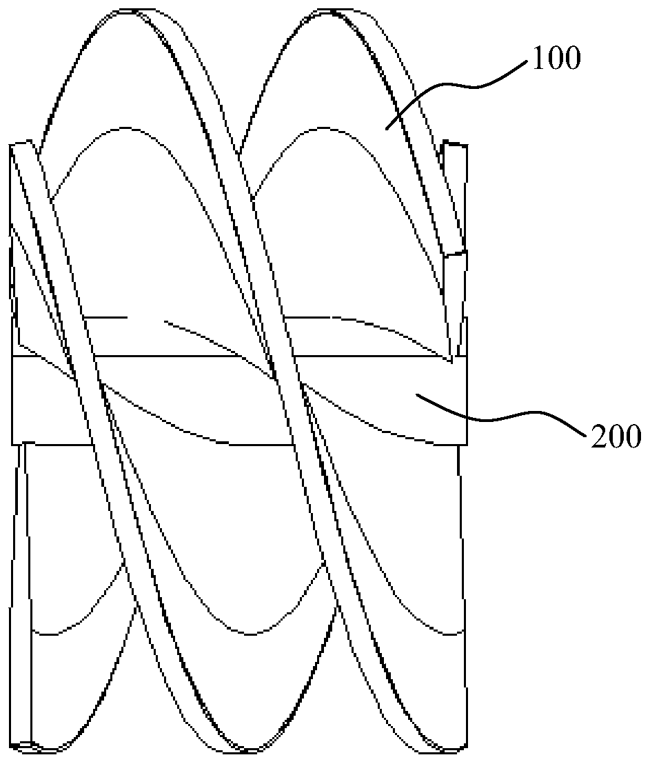
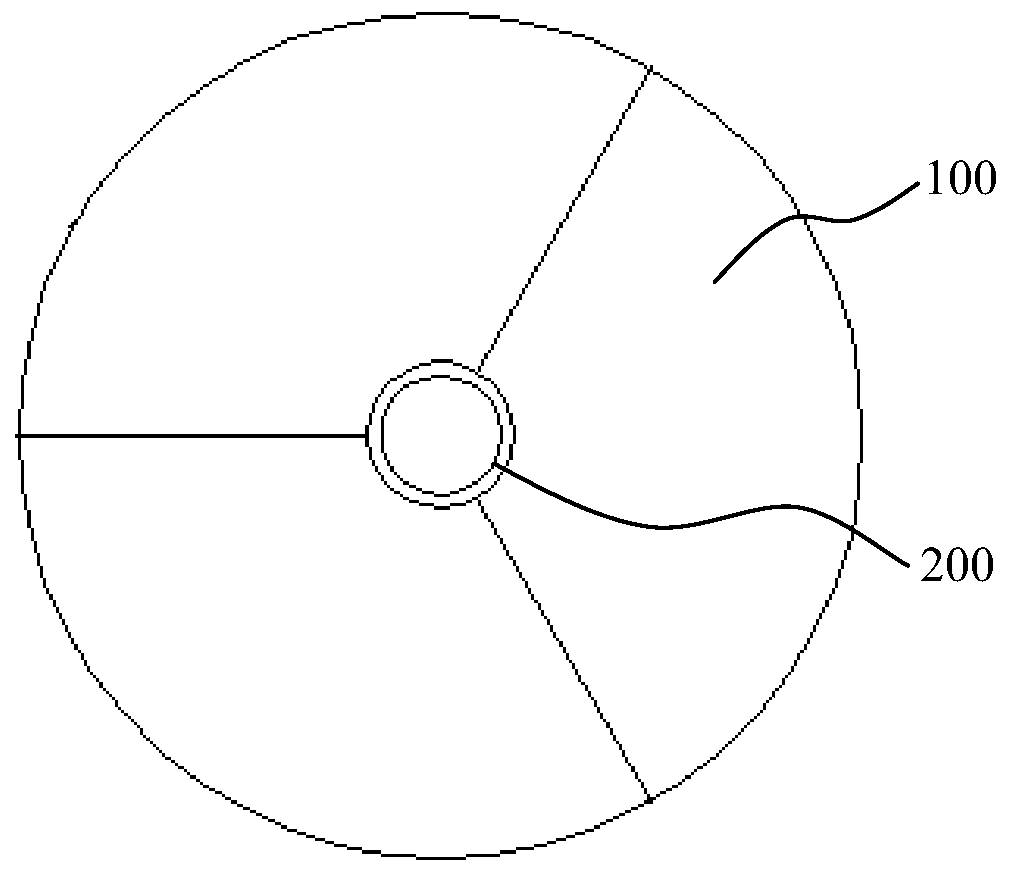
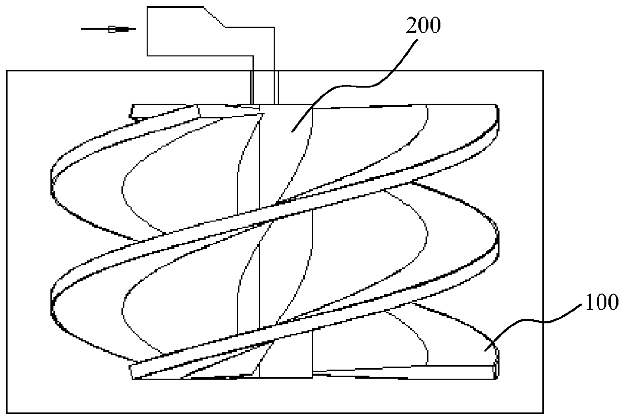
A kind of centrifugal casting stirring impeller and method
A stirring impeller and centrifugal casting technology, applied in the field of impeller production, can solve the problems of poor wear resistance, short service life, low strength, etc., and achieve the effects of simplified casting process, low cost and high productivity
- Summary
- Abstract
- Description
- Claims
- Application Information
AI Technical Summary
Problems solved by technology
Method used
Image
Examples
Embodiment 1
[0065] The method for the centrifugal casting stirring impeller of the present embodiment comprises the following specific steps:
[0066] S101, making mould: making the stirring impeller centrifugal rotation mold, the centrifugal rotation mold comprises a left template and a right template (the structure of this part and the mold of the prior art can be the same structure, but not as the focus of the present invention), the left template Fasten with the right template to form a molding cavity, the shape of the molding cavity is consistent with the outer contour of the stirring impeller, the reserved shrinkage is 3mm, and the dimensional accuracy is ±0.02mm;
[0067] S102. Alloy melting
[0068] 1) Select the first graphite crucible to melt the wheel 100 alloy at a temperature of 1600°C. The chemical composition of the wheel 100 alloy is shown in Table 1. The melt in the graphite crucible is stirred for 5 minutes and then degassed and refined to form the wheel 100. Alloy melt...
Embodiment 2
[0084] The method for the centrifugal casting stirring impeller of the present embodiment, concrete steps are basically consistent with embodiment 1, difference is:
[0085] S101. The reserved shrinkage of the stirring impeller centrifugal rotating mold is 2mm, and the dimensional accuracy is ±0.02mm;
[0086] S102. Alloy melting
[0087] 1) Select the first graphite crucible to melt the wheel 100 alloy at a temperature of 1560°C. The chemical composition of the wheel 100 alloy is shown in Table 1. The melt in the graphite crucible is stirred for 3 minutes and then degassed and refined to form the wheel 100. Alloy melt;
[0088] 2) Select the second graphite crucible to melt the hub 200 alloy at a temperature of 1600 ° C. The chemical composition of the hub 200 alloy is shown in Table 2. The melt in the graphite crucible is stirred for 3 minutes and then degassed and refined to form the hub 200 alloy melt;
[0089] S103. Centrifugal casting: use a horizontal centrifuge, plac...
Embodiment 3
[0096] The method for the centrifugal casting stirring impeller of the present embodiment, concrete steps are basically consistent with embodiment 1, difference is:
[0097] S101. The reserved shrinkage of the stirring impeller centrifugal rotating mold is 2.5mm, and the dimensional accuracy is ±0.02mm;
[0098] S102. Alloy melting
[0099] 1) Select the first graphite crucible to melt the wheel 100 alloy at a temperature of 1580°C. The chemical composition of the wheel 100 alloy is shown in Table 1. The melt in the graphite crucible is stirred for 1 minute and then degassed and refined to form the wheel 100. Alloy melt;
[0100] 2) Select the second graphite crucible to melt the hub 200 alloy at a temperature of 1560 ° C. The chemical composition of the hub 200 alloy is shown in Table 2. The melt in the graphite crucible is stirred for 3 minutes and then degassed and refined to form the hub 200 alloy melt;
[0101] S103. Centrifugal casting: use a horizontal centrifuge, pla...
PUM
| Property | Measurement | Unit |
|---|---|---|
| thickness | aaaaa | aaaaa |
| diameter | aaaaa | aaaaa |
Abstract
Description
Claims
Application Information
 - R&D
- Intellectual Property
- Life Sciences
- Materials
- Tech Scout
- Unparalleled Data Quality
- Higher Quality Content
- 60% Fewer Hallucinations
Browse by: Latest US Patents, China's latest patents, Technical Efficacy Thesaurus, Application Domain, Technology Topic, Popular Technical Reports.
© 2025 PatSnap. All rights reserved.Legal|Privacy policy|Modern Slavery Act Transparency Statement|Sitemap|About US| Contact US: help@patsnap.com


