Blowing diffusion device for paper deacidification
A diffusion device and deacidification technology, applied in waste paper post-processing, physical treatment of paper, etc., can solve the problems of occupation, affecting the efficiency of deacidification work, etc., and achieve the effect of shortening the drying time
- Summary
- Abstract
- Description
- Claims
- Application Information
AI Technical Summary
Problems solved by technology
Method used
Image
Examples
Embodiment 1
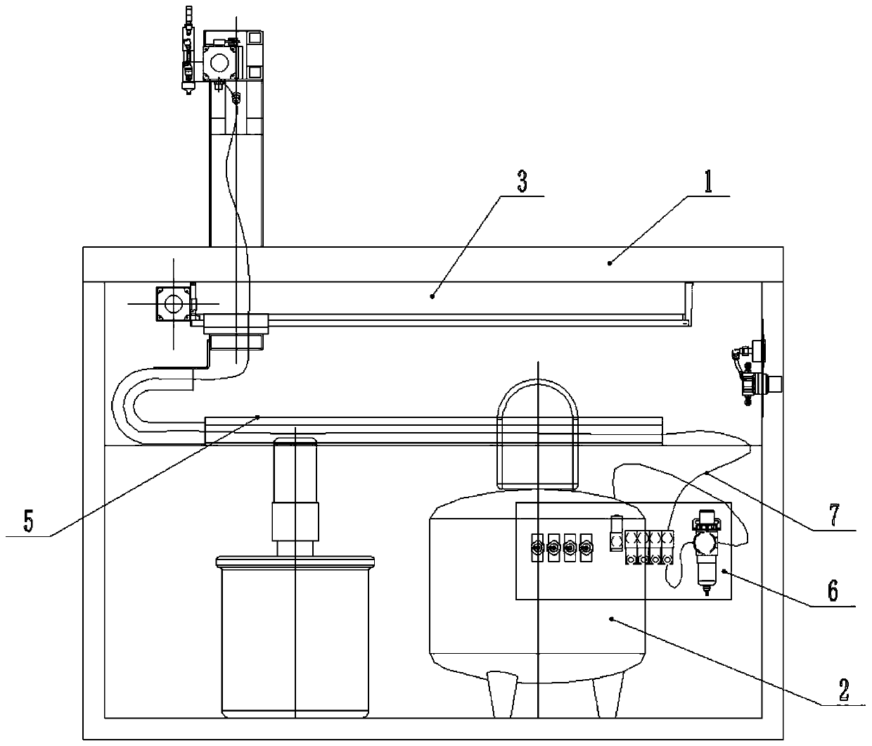
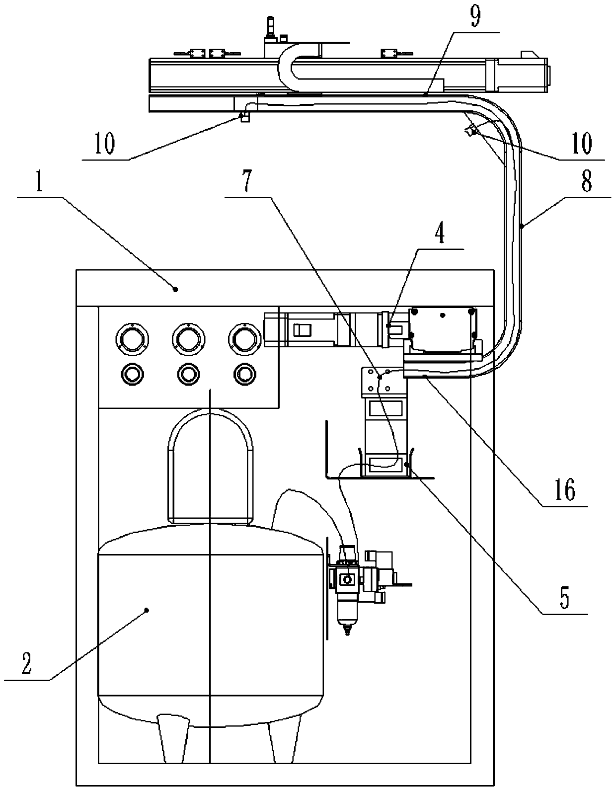
[0023] Such as figure 1 and 2 As shown, a blowing diffuser for paper deacidification includes a workbench 1, and also includes an air compressor 2, an air control valve group 6, a linear module 3, a motor 4, a support beam, an air pipe 7 and a nozzle 10, and the air compressor The machine 2 is set at the lower part of the workbench 1, the linear module 3 is installed on the lower surface of the workbench 1, the motor 4 is connected with the linear module 3, the bottom of the support beam is connected with the linear module 3, and the top of the support beam is connected with a nozzle 10 , one end of the air pipe 7 is connected to the air compressor 2 through the air control valve group 6, and the other end of the air pipe 7 is connected to the nozzle 10.
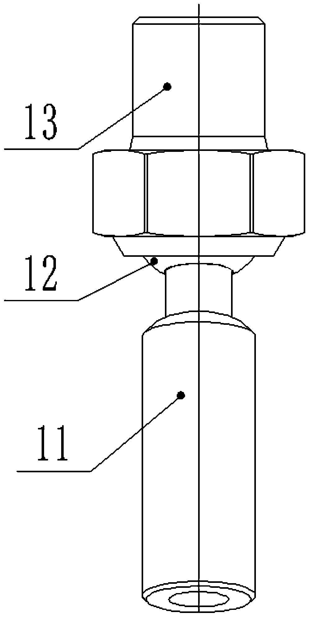
[0024] In this embodiment, the air control valve group 6 includes a solenoid valve and a throttle valve, one end of the air pipe 7 is connected to the throttle valve, the throttle valve is connected to the solenoid valve, a...
Embodiment 2
[0029] Such as figure 1 As shown, this implementation is further optimized on the basis of Embodiment 1. This embodiment focuses on the improvements compared with Embodiment 1, and the similarities will not be repeated. In this embodiment, the support beam is The opening is U-shaped to the left, and the inside of the support beam is provided with a cavity, and the air pipe 7 is arranged in the cavity. The air pipe 7 is arranged in the cavity to prevent the air pipe 7 from being knotted with the support beam or other structural parts when the support beam moves with the linear module 3 , thereby blocking the air path of the air pipe 7 . At the same time, it will also make the workstation tidy and orderly, which is convenient for cleaning and maintenance.
[0030] Specifically, the U-shaped support beam of this embodiment includes a first segment rod 16, a second segment rod 8 and a third segment rod 9 each provided with a cavity, and the first segment rod 16 is horizontally co...
Embodiment 3
[0032] Such as figure 1 As shown, this implementation is further optimized on the basis of Embodiment 2. This embodiment focuses on the improvements compared with Embodiment 1, and the similarities will not be repeated. In this embodiment, the first section of the rod The junction between 16 and the second section bar 8 is provided with a first chamfer, and the junction between the second section bar 8 and the third section bar 9 is provided with a second chamfer, installed at the second chamfer There is a spray head 10, and there is a certain angle between the spray head 10 at the second chamfer and the worktable 1. The setting of the first chamfer and the second chamfer can prevent the connection between the first section rod 16 and the second section rod 8 of the air pipe 7 and the connection between the second section rod 8 and the third section rod 9 . Blocked by edges and corners, it is knotted to block the air path of the air pipe 7, resulting in the weakening of the a...
PUM
 Abstract
Description
Claims
Application Information
 - R&D Engineer
- R&D Manager
- IP Professional
- Industry Leading Data Capabilities
- Powerful AI technology
- Patent DNA Extraction
Browse by: Latest US Patents, China's latest patents, Technical Efficacy Thesaurus, Application Domain, Technology Topic, Popular Technical Reports.
© 2024 PatSnap. All rights reserved.Legal|Privacy policy|Modern Slavery Act Transparency Statement|Sitemap|About US| Contact US: help@patsnap.com


