Honeycomb energy absorption structure and preparation method of absorption structure

An energy absorption, honeycomb technology, applied in mechanical equipment, shock absorbers, springs/shock absorbers, etc., can solve the impact conditions that cannot adapt to changes in direction, reduce the energy absorption capacity per unit mass, and increase the production process. , to simplify the industrial production process, improve the energy absorption capacity, and improve the stiffness of the unit cell

Active Publication Date: 2019-07-23
NORTHEAST FORESTRY UNIVERSITY
View PDF6 Cites 6 Cited by
  • Summary
  • Abstract
  • Description
  • Claims
  • Application Information

AI Technical Summary

Problems solved by technology

[0003] In order to solve the problem that the existing simple energy-absorbing structure is limited to a single-direction design and cannot adapt to the impact conditions of direction changes, the complex energy-absorbing structure increases the difficulty of the process and reduces the energy absorption capacity per unit mass, and further provides a Honeycomb energy absorbing structure and method for preparing the absorbing structure,

Method used


Image

  • Honeycomb energy absorption structure and preparation method of absorption structure
  • Honeycomb energy absorption structure and preparation method of absorption structure
  • Honeycomb energy absorption structure and preparation method of absorption structure

Examples


specific Embodiment approach 1

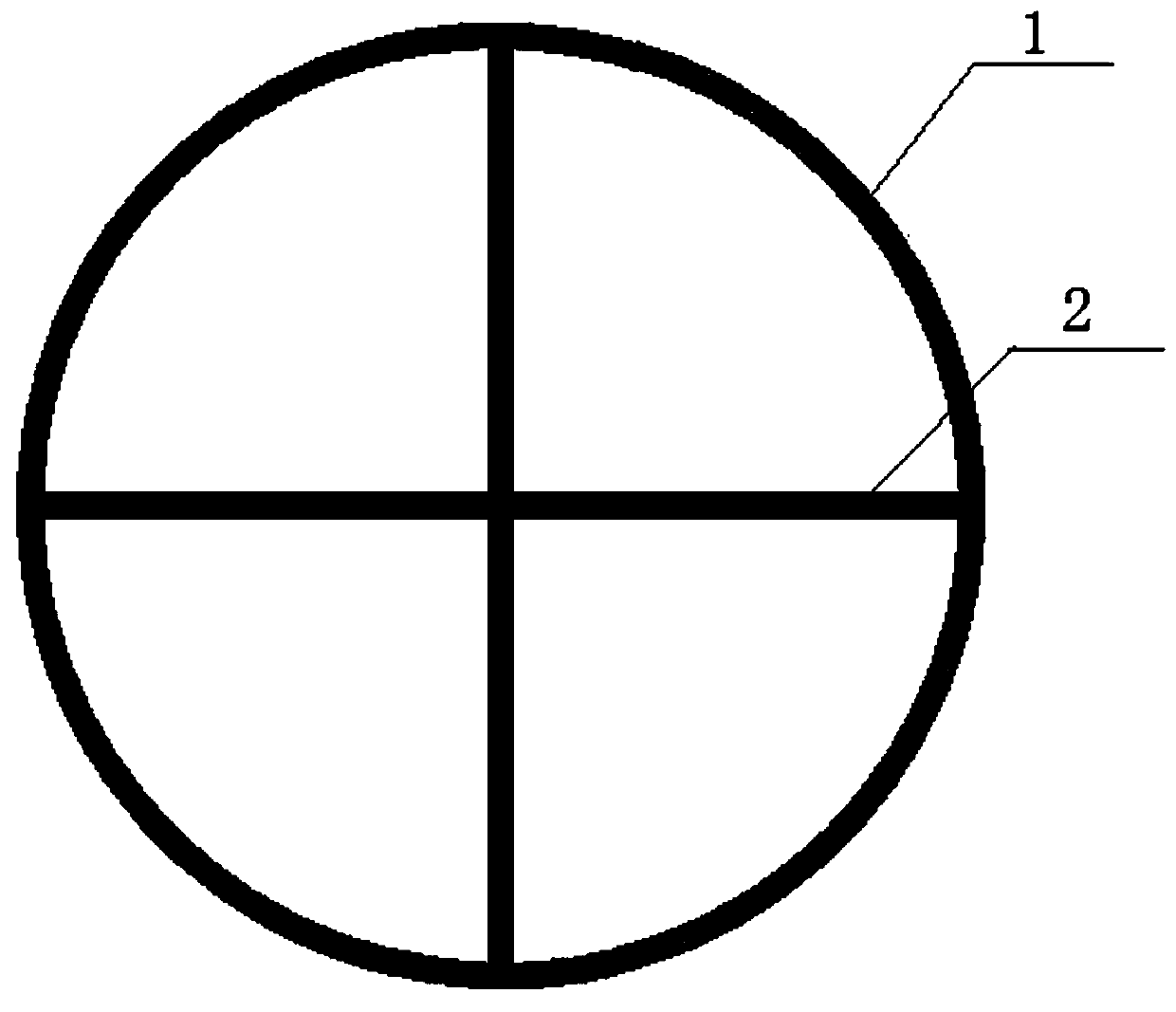
[0024] Specific implementation mode one: combine Figure 1-Figure 4 and Figure 6 Describe this embodiment, a honeycomb energy absorbing structure described in this embodiment, which includes a plurality of energy-absorbing components, each energy-absorbing component includes a circular body 1 and a 'cross' cross plate 2; a 'cross' cross plate 2 is fixedly installed on the inner wall of the torus 1, and multiple energy-absorbing components are arranged side by side in parallel to form a honeycomb energy absorption structure, and any two adjacent torus 1 are fixedly connected.

specific Embodiment approach 2

[0025] Specific implementation mode two: combination figure 1 and figure 2 Describe this embodiment, the honeycomb energy absorption structure described in this embodiment, the ring body 1 and the 'cross' cross plate 2 are made of metal materials, and other methods are the same as in the first embodiment.

specific Embodiment approach 3

[0026] Specific implementation mode three: combination figure 1 and figure 2 Describe this embodiment, the honeycomb energy absorbing structure described in this embodiment, the length of the annular body 1 along the axial direction is equal to the length of the cross plate 2 along the longitudinal direction. Other methods are the same as in the first embodiment.


PUM


Abstract

The invention provides a honeycomb energy absorption structure and a preparation method of the absorption structure, and relates to an energy absorption structure and a preparation method of the absorption structure. The honeycomb energy absorption structure and the preparation method of the absorption structure aim at solving the problems that an existing simple energy absorption structure is confined to single direction design and cannot adapt to impact conditions with the direction change, and in a complex energy absorption structure, the difficulty of the process manufacturing flow is increased, and the energy absorption capacity in unit mass is reduced. The honeycomb energy absorption structure comprises multiple energy absorption assemblies. The multiple energy absorption assembliesare arranged side by side in parallel to form the honeycomb energy absorption structure. The method is achieved through the following steps that 1, aluminum alloy or stainless steel metal plates are cut through the linear cutting technology; 2, the plates cut in the step 1 and annular pipe bodies are sequentially cleaned, subjected to oil stain removal and subjected to rust removal; 3, cross plates are welded to the inner side walls of ring bodies, and the energy absorption assemblies are manufactured; and 4, the multiple energy absorption assemblies prepared in the step 3 are arranged rectangularly. The honeycomb energy absorption structure and the preparation method of the energy absorption structure are used in the field of energy absorption structures.

Description

technical field [0001] The invention relates to an energy absorbing structure and a preparation method of the absorbing structure, in particular to a honeycomb energy absorbing structure and a preparation method of the absorbing structure. Background technique [0002] The energy absorbing structure is a common safety protection device and is widely used in In large-scale industrial engineering fields such as aerospace, vehicle engineering, and ocean engineering, the occurrence of impact collision accidents has been avoided, and casualties and property losses have been reduced or reduced. At present, the structure of honeycomb energy absorbing unit cell has developed from simple quadrilateral, hexagonal and ring to complex rotational quadrilateral and chiral structure. Although these structures can control Poisson's ratio, they reduce the energy absorption capacity per unit mass. The complex energy-absorbing structure increases the difficulty of the manufacturing process. ...

Claims


Application Information

Patent Timeline
Patent Type & Authority Applications(China)
IPC IPC(8): F16F7/12
CPCF16F7/121F16F7/128
Inventor 吴鹤翔
Owner NORTHEAST FORESTRY UNIVERSITY
Why Eureka
Try Eureka