Boulder detection method and device thereof

A detection method and technology for boulders, applied in the field of geological survey, can solve the problems of inability to obtain parameters for the size of the boulder space, troublesome construction, missing boulders, etc., so as to improve the detection efficiency and accuracy, good adaptability and practicality. Sensitivity, the effect of a large detection area

Active Publication Date: 2019-07-23
广东有色工程勘察设计院
View PDF8 Cites 0 Cited by
  • Summary
  • Abstract
  • Description
  • Claims
  • Application Information

AI Technical Summary

Problems solved by technology

[0003] In the current geological exploration methods, the exploration of boulders (blocks) is mainly drilling and ground geophysical prospecting. Because the distribution of boulders in the stratum is random, and the particle size and burial depth are different, the drilling method requires high Density drilling can only reveal part of it. Due to the limitation of drilling diameter and drilling density, some boulders will still be missed and cannot be detected one by one. Part of the boulder, the space size of the boulder is still unable to obtain accurate parameters, which brings a lot of waste of resources to the boulder processing
The use of geophysical prospecting methods is limited by the resolution of the equipment, the buried depth and size of the boulder, and the location and size of the boulder cannot be accurately detected. The detection results cannot be directly applied to the construction of the tunnel boulder treatment, which will cause serious damage to the construction. A certain hassle, this needs to be improved

Method used


Image

  • Boulder detection method and device thereof
  • Boulder detection method and device thereof
  • Boulder detection method and device thereof

Examples


Embodiment 1

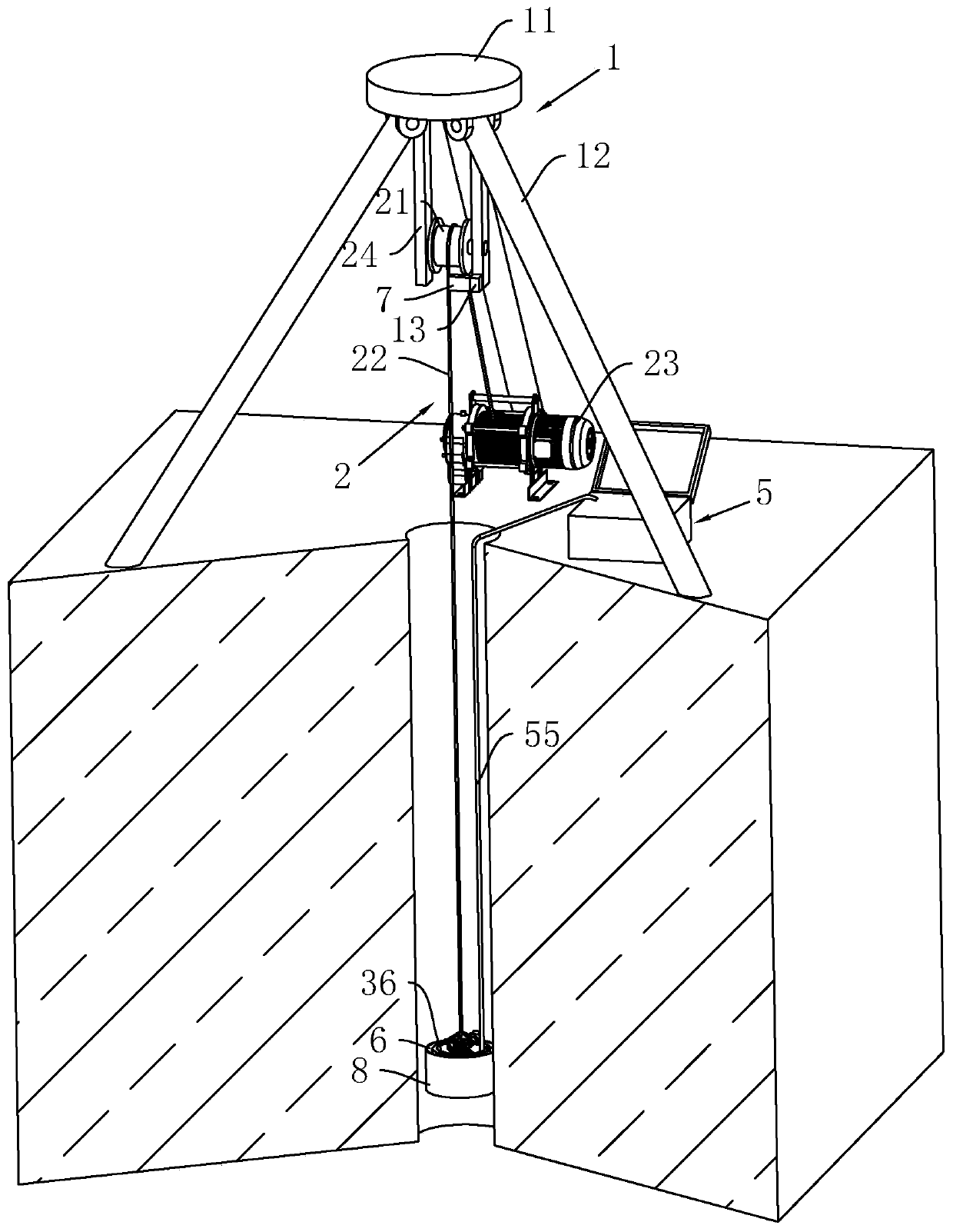
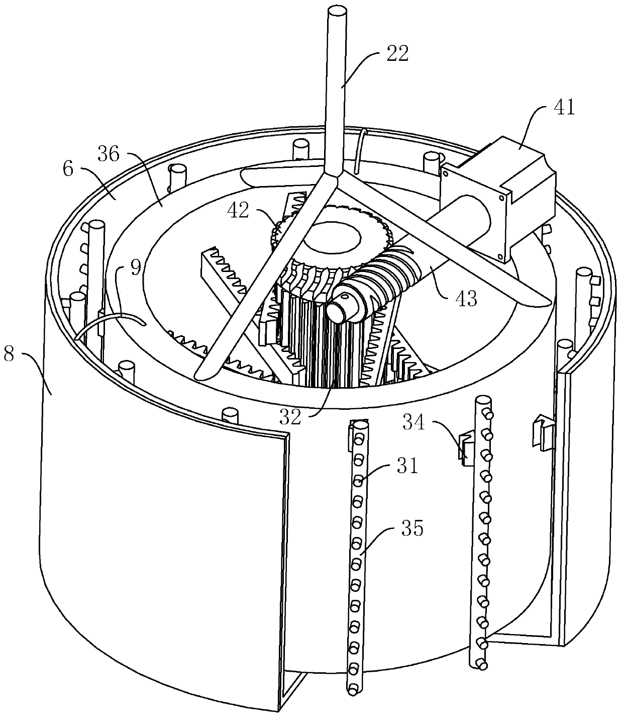
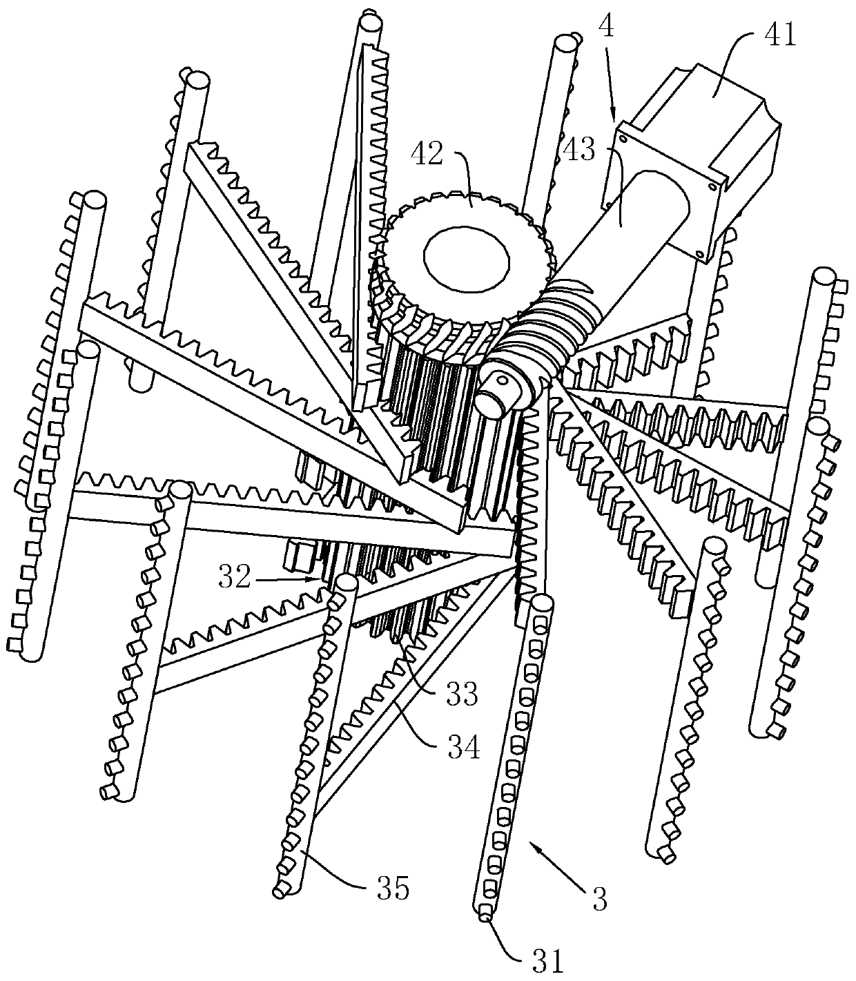
[0046] refer to figure 1 , is the downhole ultrasonic detector disclosed by the present invention, comprising a mounting frame 1 installed above the wellhead, on the mounting frame 1 is hoisted a lifting device 2 towards the inside of the well, an ultrasonic probe 3 is arranged on the lifting device 2, and an ultrasonic probe 3 is arranged inside There are several ultrasonic transducers 31 and the driving device 4 that drives several ultrasonic transducers 31 to approach or move away from the hole wall synchronously, and also includes a receiving device arranged on the ground, and the receiving device is connected to the ultrasonic probe 3 through a wireless or wired connection. .

[0047] Mounting frame 1 comprises three support rods 12 hinged on the same support plate 11, triangular in shape when three support rods 12 are stretched out, support plate 11 is placed on wellhead, and three support rods 12 are placed around the wellhead circumference. The lifting device 2 includ...

Embodiment 2

[0067] A boulder detection method, comprising the following steps:

[0068] S1 drilled holes for detection, details are as follows:

[0069] Drilling holes on the ground with a diameter of 168mm and a final hole of 91mm;

[0070] S2 detection, as follows:

[0071] Extend the ultrasonic detector into the detection hole, the ultrasonic detection equipment is provided with an ultrasonic probe 3, and a plurality of ultrasonic transducers 31 are arranged in the ultrasonic probe 3, and several ultrasonic transducers 31 driving the ultrasonic detector are pressed against the detection hole at the same time On the hole wall, ultrasonic detection is carried out. When the detection hole drilled for the first time is a soil layer, the ultrasonic probe 3 is put into the detection hole by the winding rope 22, and the driving motor 41 drives the ultrasonic transducer 31 so that the ultrasonic transducer 31 It is vertically coupled with the hole wall, and the ultrasonic probe 3 is turned o...


PUM


Abstract

The invention relates to a boulder detection method, which comprises the following steps: putting an ultrasonic probe on a position to be detected through a drill hole, starting a driving device, driving a plurality of ultrasonic transducers in the direction vertical to the hole wall of a detection hole to ensure that the ultrasonic probe is tightly attached to and coupled with the hole wall of the detection hole, then detecting by using ultrasonic waves to obtain the accurate spatial position of a wave-facing surface of a boulder, transmitting data to a control computer through a data line, and generating the three-dimensional spatial position and size of the boulder in proportion. The method for detecting the boulders through the ultrasonic waves can greatly reduce the workload of exposing the boulders in the traditional exploration method, save a large amount of cost, effectively avoid the problems of boulder omission, low accuracy and the like caused by the boulder exploration in the traditional exploration method, improve the working efficiency of boulder exploration, improve the accuracy of boulder exploration and reduce the engineering construction risk.

Description

technical field [0001] The invention relates to the technical field of geological survey, in particular to a boulder detection method and equipment thereof. Background technique [0002] In the field of geological exploration, urban rail and transportation, railways, water tunnels, etc., when the shield method is used for construction, the weathered boulders remaining in the spherical weathering in the stratum and the large-grained rocks in the alluvial and diluvial layers have a great impact on the shield tunneling. Serious adverse effects on construction safety. [0003] In the current geological exploration methods, the exploration of boulders (blocks) is mainly drilling and ground geophysical prospecting. Because the distribution of boulders in the stratum is random, and the particle size and burial depth are different, the drilling method requires high Density drilling can only reveal part of it. Due to the limitation of drilling diameter and drilling density, some bou...

Claims


Application Information

Patent Timeline
Patent Type & Authority Applications(China)
IPC IPC(8): G01V1/44
CPCG01V1/44
Inventor 苏再非徐力峰陈杰强沈秋华周国粱
Owner 广东有色工程勘察设计院
Why Eureka
Try Eureka