Dielectric waveguide filter and capacitive coupling structure thereof

A capacitive coupling, dielectric waveguide technology, applied in the field of filters, can solve problems such as easy penetration, inability to guarantee production quality, and influence on sintering molding.

Pending Publication Date: 2019-07-23
COMBA TELECOM TECH (GUANGZHOU) CO LTD +1
View PDF0 Cites 9 Cited by
  • Summary
  • Abstract
  • Description
  • Claims
  • Application Information

AI Technical Summary

Problems solved by technology

In order to achieve the purpose of capacitive coupling, traditional dielectric waveguide filters usually adopt the following two forms: 1. Adopt the form of deep holes, and control the capacitive coupling bandwidth by adjusting the distance between the hole depth and the surface of the dielectric waveguide filter. The smaller the capacitive coupling bandwidth is, the narrower the capacitive coupling bandwidth is. Therefore, to achieve a narrow capacitive coupling bandwidth, the spacing will be quite small, which will affect the sintering molding and increase the difficulty of sintering. The problem of puncture is also prone to occur during the production process, and the corresponding increase Difficulty in production; 2. Adopt the form of a through hole, and set a closed ring concentric with the through hole in the circumferential direction of the through hole. By adjusting the width of the ring, the narrower the width, the narrower the capacitive coupling bandwidth. Therefore, it is necessary to To achieve a narrow capacitive coupling bandwidth, the distance between the outer diameter and inner diameter of the ring will be quite small, resulting in uncontrollable errors in the production process and increasing the risk of short circuits
Therefore, the capacitive coupling structure of the traditional dielectric waveguide filter is difficult to produce, the production quality cannot be guaranteed, and it is not conducive to mass production

Method used


Image

  • Dielectric waveguide filter and capacitive coupling structure thereof
  • Dielectric waveguide filter and capacitive coupling structure thereof
  • Dielectric waveguide filter and capacitive coupling structure thereof

Examples


Embodiment Construction

[0031] In order to make the object, technical solution and advantages of the present invention clearer, the present invention will be further described in detail below in conjunction with the accompanying drawings and specific implementation methods. It should be understood that the specific embodiments described here are only used to explain the present invention, and do not limit the protection scope of the present invention.

[0032]It should be noted that when an element is referred to as being “disposed on” or “fixed on” another element, it may be directly on another element or there may be an intervening element. When an element is referred to as being "fixed on" another element, or "fixedly connected" to another element, it may be detachably fixed or non-detachably fixed therebetween. When an element is referred to as being "connected" or "rotatably connected" to another element, it can be directly connected to the other element or intervening elements may also be prese...


PUM


Abstract

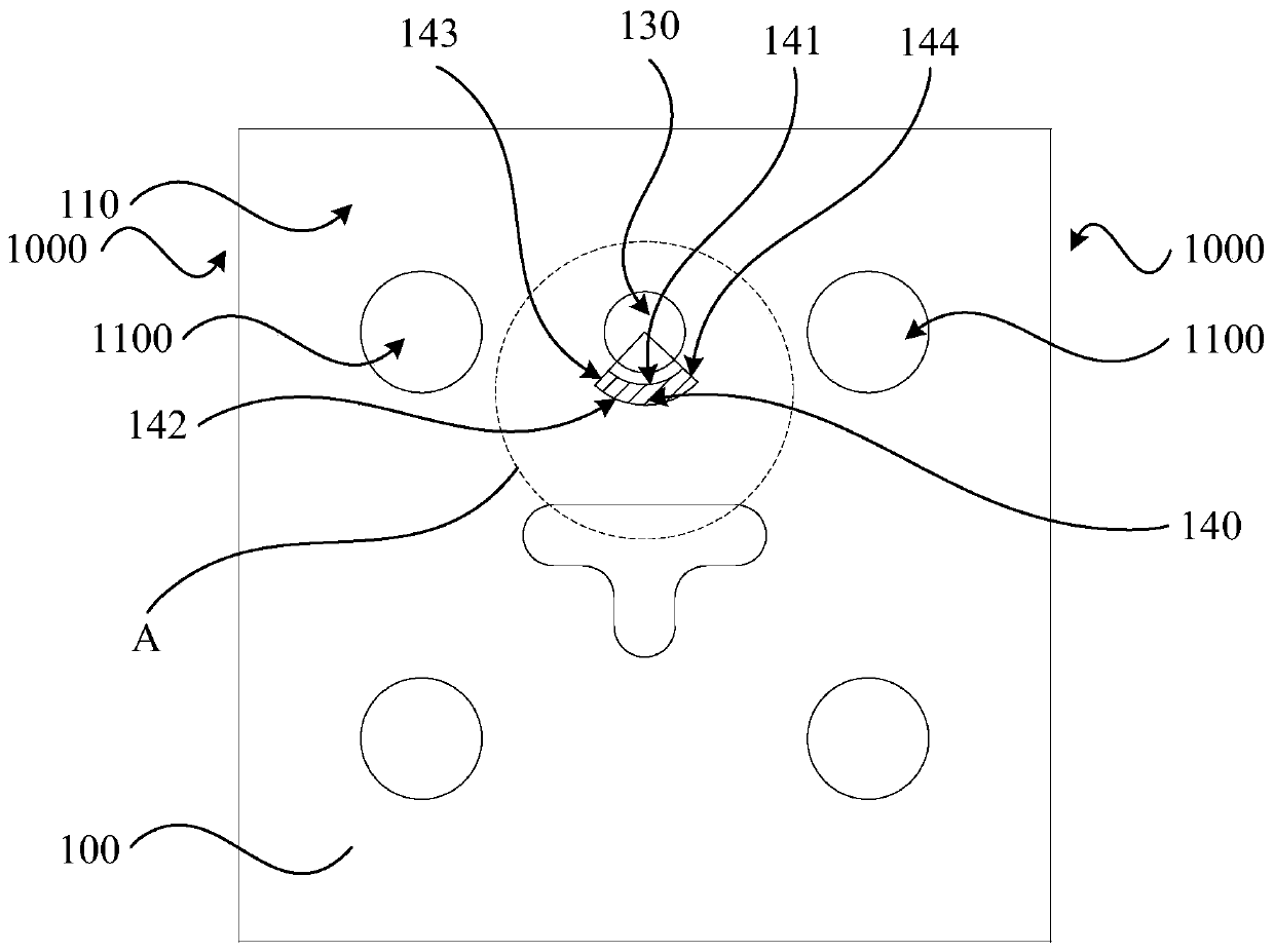
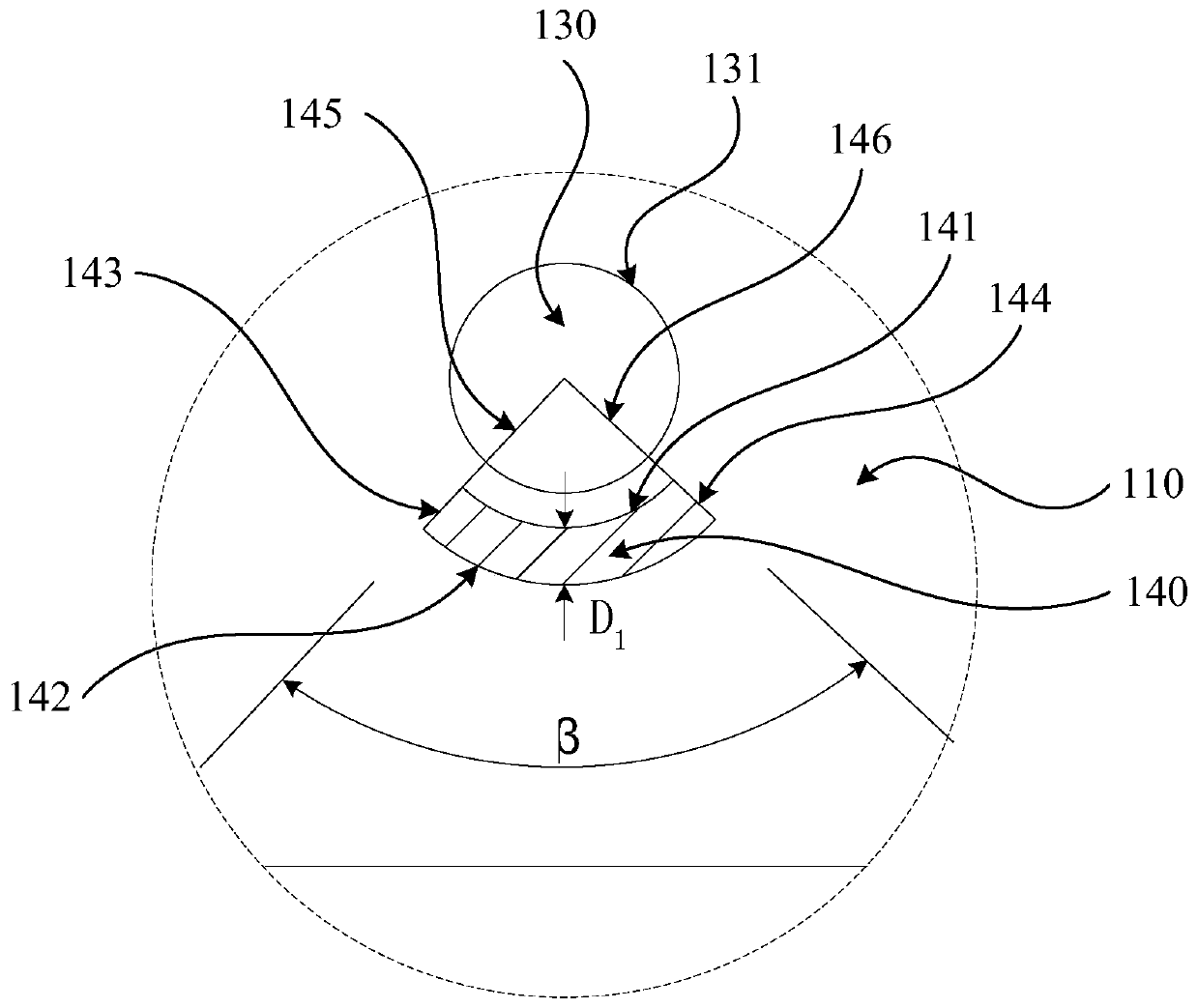
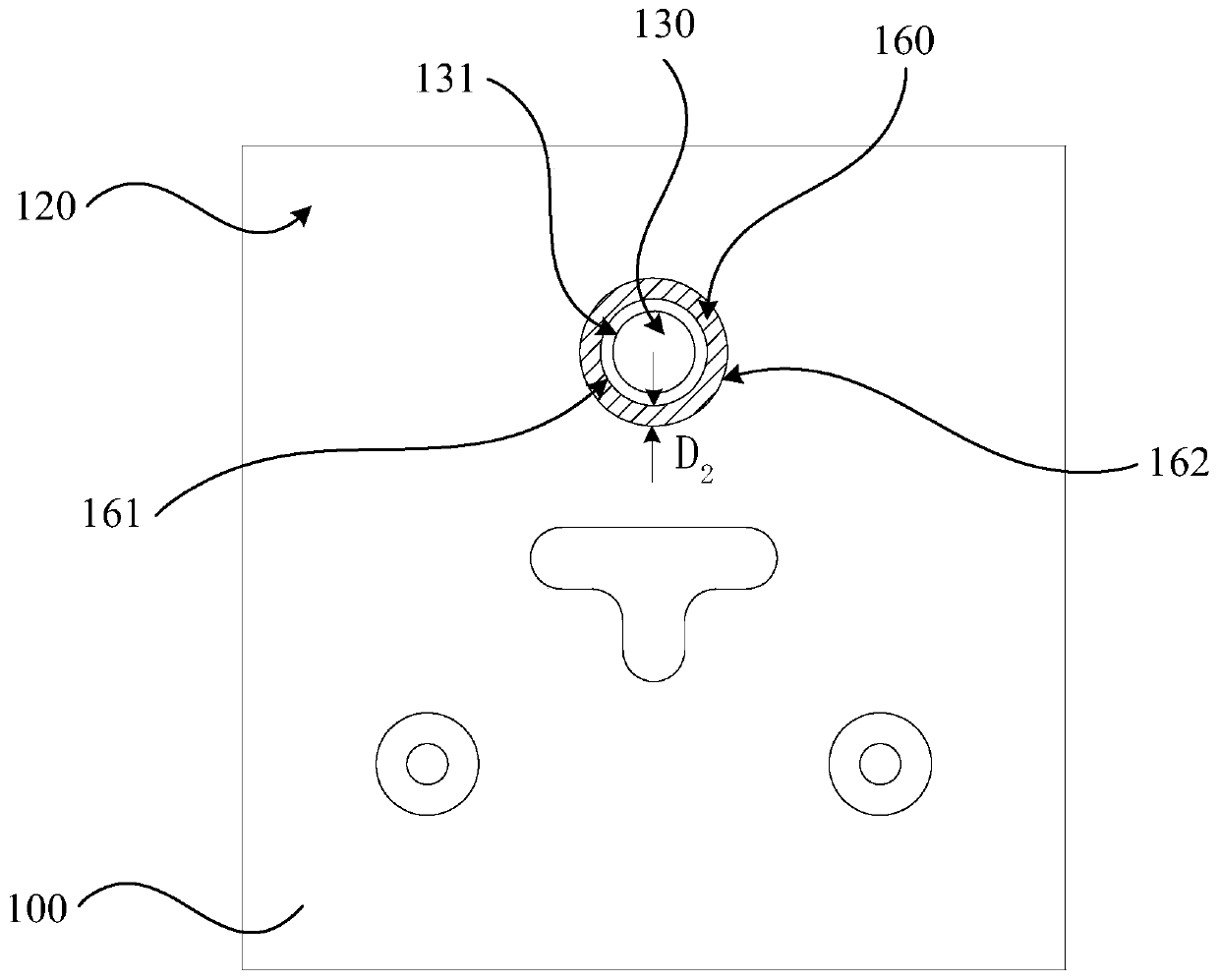
The invention discloses a dielectric waveguide filter and a capacitive coupling structure thereof. The capacitive coupling structure comprises a through hole arranged between two adjacent dielectric resonators in a dielectric body. The dielectric body is provided with a first surface and a second surface which are oppositely arranged at an interval; the through hole penetrates through the first surface and the second surface; a first adjusting groove is formed in the first surface; the first adjusting groove is formed in the circumferential direction of the through hole. The first adjusting groove is arranged in a non-closed mode and penetrates through a first conductive layer of the first surface, the second surface is provided with a second adjusting groove, the second adjusting groove is arranged in the circumferential direction of the through hole, the second adjusting groove is arranged in a closed mode, and the second adjusting groove penetrates through a second conductive layerof the second surface. The capacitive coupling structure is convenient to process and low in production difficulty, and the production quality can be ensured; therefore, the dielectric waveguide filter adopting the capacitive coupling structure is low in production difficulty, high in production quality and suitable for mass production.

Description

technical field [0001] The invention relates to the technical field of filters, in particular to a dielectric waveguide filter and a capacitive coupling structure thereof. Background technique [0002] As a frequency selection device, a filter is a very important component in communication equipment. With the rapid development of communication technology and entering the 5G era, the miniaturization of communication devices has become a future development trend. Dielectric waveguide filters have been widely used in 5G communication equipment due to their miniaturization characteristics. [0003] The dielectric waveguide filter improves the air filling form of the traditional waveguide filter into a high dielectric constant ceramic material filling. The ceramic dielectric material is molded by die-casting and plays the role of signal transmission and structural support. At the same time, the metal outer layer is attached to the surface of the ceramic dielectric material as ...

Claims


Application Information

Patent Timeline
Patent Type & Authority Applications(China)
IPC IPC(8): H01P1/20
CPCH01P1/2002
Inventor 谢懿非丁海邸英杰林显添
Owner COMBA TELECOM TECH (GUANGZHOU) CO LTD
Why Eureka
Try Eureka