
Patsnap Eureka
For R&D, Patsnap Eureka makes reading and utilizing patents & technical documents easy.
Patsnap Eureka AIR
Designed for self-driven R&D workflows. Generate viable solutions, solve complex R&D challenges, empower your innovation with AI.

Patsnap Eureka Materials
Designed for material experts only. Revolutionize your material R&D, from search, analyze, to developing new materials.

TechResearch
Generate reliable direction feasibility study reports for your R&D in just a few steps.

TechSeek
Discover and master advanced knowledge NOW. Basics, ideas, possibilities, all at once.

TechMind
As an expert in R&D Theories, TechMind can generates customized viable solutions instantly.

TechRisk
Analyze your overall solution with one click, know your potential R&D risks in advance.

TechMonitor
Get weekly tech updates, stay abreast of the latest tech innovations and key insights.
Sequential infiltration synthesis apparatus
A technology for synthesizing equipment and equipment, applied in the direction of optomechanical equipment, instruments, coatings, etc., can solve the problems of low etching resistance, difficult transfer, etc., and achieve the effect of increasing throughput
- Summary
- Abstract
- Description
- Claims
- Application Information
AI Technical Summary
Problems solved by technology
Method used
Image

Examples
Embodiment Construction
[0032] While certain embodiments and examples are disclosed below, those skilled in the art will appreciate that the invention extends beyond the specifically disclosed embodiments and / or uses of the invention as well as obvious modifications and equivalents thereof. Therefore, it is intended that the scope of the present disclosure should not be limited by the specific disclosed embodiments described below.
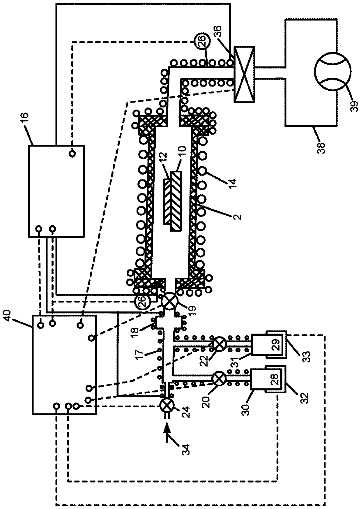
[0033] figure 1 Depicted is a sequential osmosis synthesis apparatus according to an embodiment. The apparatus comprises a reaction chamber 2 made of a suitable material such as steel, aluminum or quartz. A substrate 12 topped with a permeable material can be placed on a substrate holder 10 in the reaction chamber 2 via a substrate opening (not shown) by a substrate handler. The reaction chamber 2 forms a chamber closed at one end by a flange through which gas is introduced via one or more openings provided with at least one (distribution) reaction chamber valve 19 for...
PUM
 Abstract
Description
Claims
Application Information
 - R&D Engineer
- R&D Manager
- IP Professional
- Industry Leading Data Capabilities
- Powerful AI technology
- Patent DNA Extraction
Browse by: Latest US Patents, China's latest patents, Technical Efficacy Thesaurus, Application Domain, Technology Topic, Popular Technical Reports.
© 2024 PatSnap. All rights reserved.Legal|Privacy policy|Modern Slavery Act Transparency Statement|Sitemap|About US| Contact US: help@patsnap.com