Self-suction type sac cavity flusher
A irrigator and self-priming technology, which is applied in the field of dental medical equipment and medical equipment, can solve the problems of stasis cavity, infection, pollution, etc., and achieve the effect of improving the flushing effect, ensuring cleanliness, and promoting the recovery of the affected area
- Summary
- Abstract
- Description
- Claims
- Application Information
AI Technical Summary
Problems solved by technology
Method used
Image

Examples
Embodiment 1
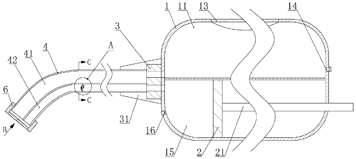
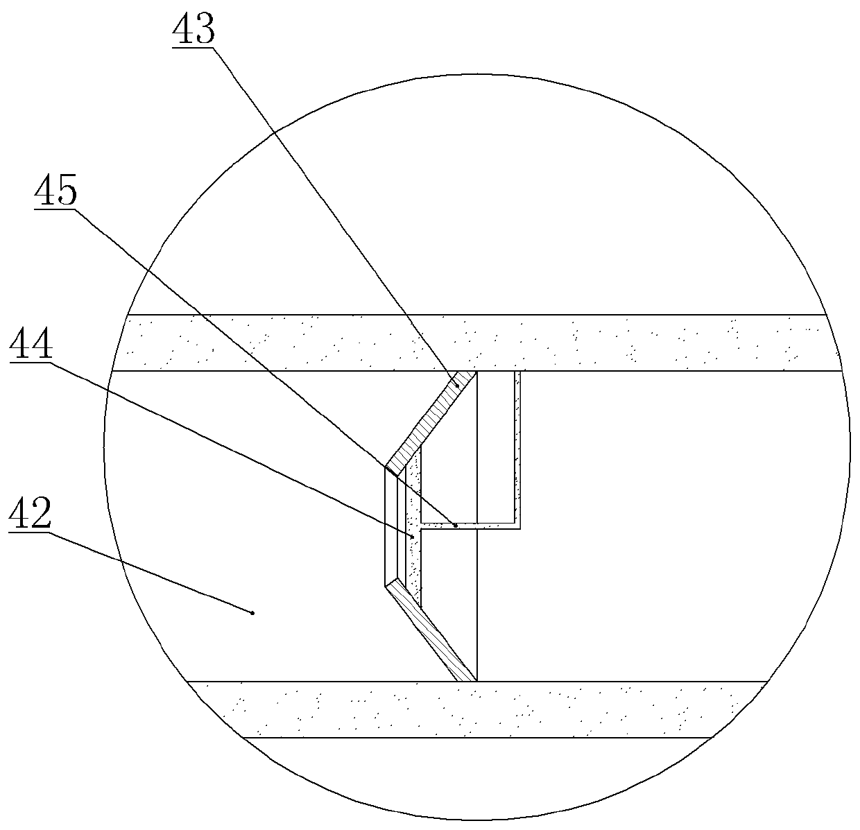
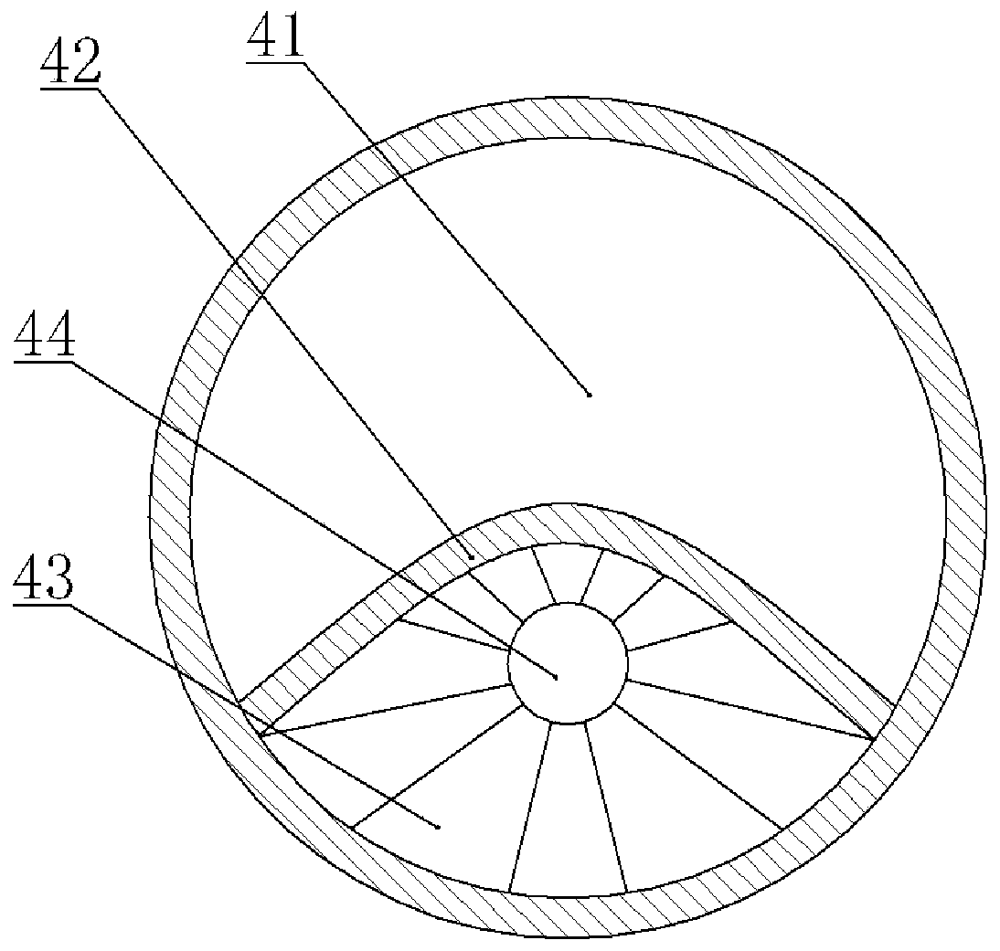
[0041] Embodiment 1 is basically as attached figure 1 , figure 2 , image 3 with Figure 4 Shown:
[0042]Self-priming bladder flusher, from right to left, includes a handle, an adapter 31 and a flushing suction head 4, the handle includes a push mechanism, a bottle body 1 and a suction mechanism, and the bottle body 1 is provided with a suction chamber 11 and the cavity below the suction cavity 11, there is a piston 2 vertically in the cavity, the piston 2 is connected with the cavity horizontally and slidingly, and the left side of the piston 2 is a flushing cavity 15. The side wall of the flushing chamber 15 is provided with a liquid inlet 16 and a liquid inlet plug, and the outer diameter of the liquid inlet plug is greater than the diameter of the liquid inlet 16, so the liquid inlet plug snaps into the liquid inlet 16 and then closes the liquid inlet 16. The pushing mechanism in this embodiment is the piston rod 21, the piston rod 21 is located on the right side of ...
Embodiment 2
[0052] Embodiment 2 is basically as attached Figure 5 with Image 6 Shown:
[0053] The difference from Embodiment 1 is that in this embodiment, a water bag 22 is provided on the left side of the piston 2, and the inner cavity of the water bag 22 is a flushing chamber 15, and a water inlet pipe is glued on the bottle body 1, and the water inlet pipe connects the water bag 22 and liquid inlet 16. The left end of the water bag 22 is glued to the left end of the flushing cavity 15, and the left end of the water bag 22 is provided with a through hole aligned with the flushing hole.
[0054] Secondly, the pushing mechanism of this embodiment is different from that of Embodiment 1. The pushing mechanism in this embodiment is located in the flushing chamber 15, including a lever 24, a push rod 23, a connecting rod 27 and three groups of scissor-type telescopic assemblies. The lever 24 is located in The upper part of the flushing chamber 15, the middle part of the lever 24 is rota...
Embodiment 3
[0058] Embodiment 3 is basically as attached Figure 7 And attached Figure 8 Shown:
[0059] Compared with Embodiment 1, in this embodiment, the flushing chamber 15 of the flushing device is not provided with a piston 2, and the pushing mechanism is different from that of Embodiment 1. The pushing mechanism of this embodiment is the second elastic piece 28, and the bottle body 1 The bottom is provided with a flushing opening, and the second elastic sheet 28 is glued to the bottom of the bottle body 1 to close the flushing opening. When flushing, pressing the second elastic sheet 28 can cause the flushing liquid in the flushing chamber 15 to flow out from the flushing channel.
[0060] The flushing and suction head 4 in this embodiment is made of two medical PVC hoses, one of which has an inner diameter of 0.5 cm and the other has an inner diameter of 1 cm, and the inner diameter of the 1 cm hose is sleeved on the other The outer side, that is, the hose with an inner diamete...
PUM
| Property | Measurement | Unit |
|---|---|---|
| Length | aaaaa | aaaaa |
Abstract
Description
Claims
Application Information
 - R&D
- Intellectual Property
- Life Sciences
- Materials
- Tech Scout
- Unparalleled Data Quality
- Higher Quality Content
- 60% Fewer Hallucinations
Browse by: Latest US Patents, China's latest patents, Technical Efficacy Thesaurus, Application Domain, Technology Topic, Popular Technical Reports.
© 2025 PatSnap. All rights reserved.Legal|Privacy policy|Modern Slavery Act Transparency Statement|Sitemap|About US| Contact US: help@patsnap.com