
Automatic paint spraying assembly line for plastic parts

An automatic painting and assembly line technology, applied in painting booths, spraying devices, etc., can solve problems such as susceptibility, human hazards, and difficulty in ensuring the quality of plastic parts painting, so as to save time, improve work efficiency, and reduce occupational diseases. risk effect

Inactive Publication Date: 2019-07-26
ZHEJIANG LAISIAO ELECTRIC
View PDF10 Cites 10 Cited by
  • Summary
  • Abstract
  • Description
  • Claims
  • Application Information

AI Technical Summary

Problems solved by technology

[0002] At present, the spraying process of plastic parts generally adopts the method of manual spraying, but the paint gas generated during the spraying process has certain harm to the human body. The staff who have been in this environment for a long time are prone to related diseases. Work is difficult to ensure the painting quality of plastic parts

Method used


Image

  • Automatic paint spraying assembly line for plastic parts
  • Automatic paint spraying assembly line for plastic parts
  • Automatic paint spraying assembly line for plastic parts

Examples


Embodiment 1

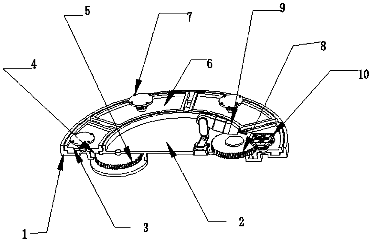
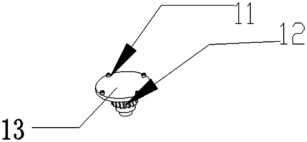
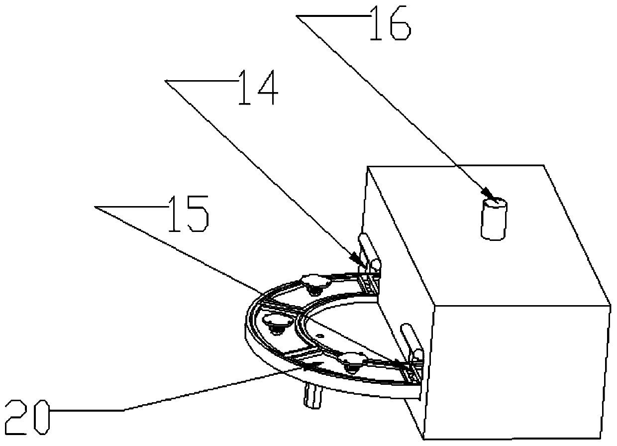
[0035] Embodiment 1: as Figure 1-Figure 3 As shown, a turntable for an automatic painting station includes a turntable installation frame and a turntable installed in the turntable installation frame 1. The turntable installation frame 1 includes a circular tray with a vertical side wall and a support frame; The fixed disk 2 and the rotating disk 3 with straight side walls, the fixed disk 2 is concentrically fixed on the upper surface of the circular tray, the vertical side wall of the fixed disk 2 and the vertical side wall of the circular tray form a slide rail, and the rotating disk 3 is installed on the Inside the slide rail; 6 stations 6 are uniformly arranged on the rotating disk 3, and each station 6 is respectively provided with a workpiece clamping tool 7; the bottom surface of the rotating disk 3 is provided with an internal gear 4, and the bottom surface of the fixed disk 2 is connected with a circular tray. A power gear 5 meshing with the internal gear 4 is arrang...

Embodiment 2

[0047] Embodiment 2: The closed paint spray booth can also be used in conjunction with the commonly used linear workbench by changing the positions of the inlet and outlet. The feed inlet and outlet of the closed paint spray booth are respectively set in On the opposite side wall of the main body, the linear workbench passes through the material inlet and outlet, runs through the main body, advances according to the rhythm, and turns around. In the middle painting station, a painting robot is set up for automatic painting, and the robot performs automatic painting. The principle and procedure are the same as those in the first embodiment.


PUM


Abstract

The invention provides an automatic paint spraying assembly line for plastic parts. The automatic paint spraying assembly line comprises an automatic paint spraying station rotary disc, a closed paintspraying chamber, a feeding frame and a drying tunnel. The automatic paint spraying station rotary disc comprises a rotary disc mounting frame and a rotary disc mounted in the rotary disc mounting frame. The rotary disc mounting frame is provided with a round tray with a vertical side wall, and a supporting frame. The rotary disc comprises a fixed disc with a vertical side wall arranged on the edge, and a rotating disc, and the rotating disc is mounted in a sliding rail. The rotating disc is provided with multiple stations, and workpiece clamping tools are arranged in the stations. An inner gear engaged with a power gear is arranged on the bottom face of the rotating disc. The fixed disc is provided with a tool power gear engaged with tool gears. An automatic paint spraying robot is further arranged on the fixed disc. The portion, provided with the automatic paint spraying robot, of the automatic paint spraying station rotary disc is located in a body. The feeding frame is put on theside, close to a feed port, of the automatic paint spraying station rotary disc, and the drying tunnel is put in the side, close to a discharge port, of the automatic paint spraying station rotary disc. Automatic paint spraying of the plastic parts is achieved.

Description

technical field [0001] The invention relates to a painting production line, in particular to an automatic painting production line for plastic parts. Background technique [0002] At present, the spraying process of plastic parts generally adopts the method of manual spraying, but the paint gas generated during the spraying process has certain harm to the human body. It is difficult to ensure the painting quality of plastic parts at work. Therefore a kind of can automatic painting, and the device that can guarantee painting efficiency is the product that is badly in need of on the market. Contents of the invention [0003] In order to solve the above problems, the present invention provides the following solutions: [0004] An automatic painting assembly line for plastic parts, including an automatic painting station turntable, a closed paint spraying room, a feeding rack and a drying tunnel; [0005] The turntable of the automatic painting station includes a turntable ...

Claims


Application Information

Patent Timeline
Patent Type & Authority Applications(China)
IPC IPC(8): B05B16/20B05B13/02B05B13/04B05B14/43B05B14/465
CPCB05B13/0242B05B13/0442B05B14/43B05B14/465B05B16/20
Inventor 王永麟姚松良姚惠民
Owner ZHEJIANG LAISIAO ELECTRIC
Learn More