
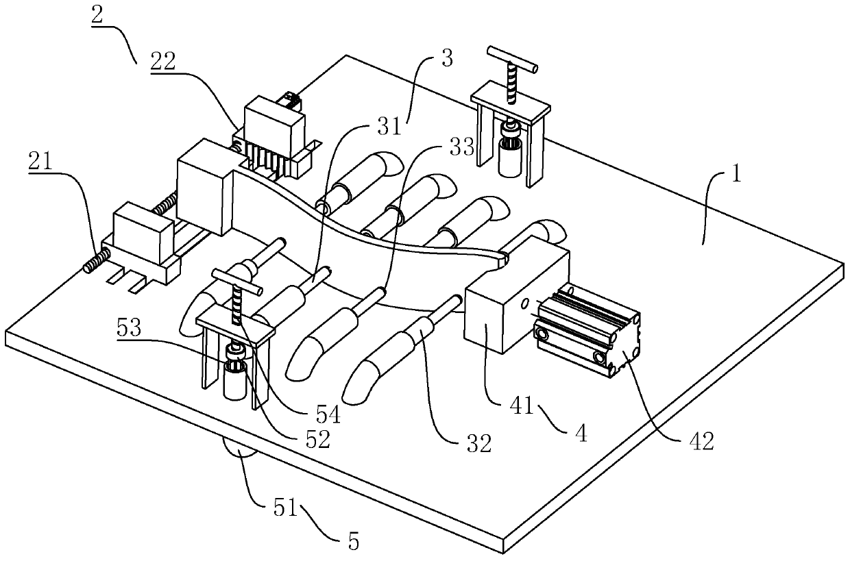
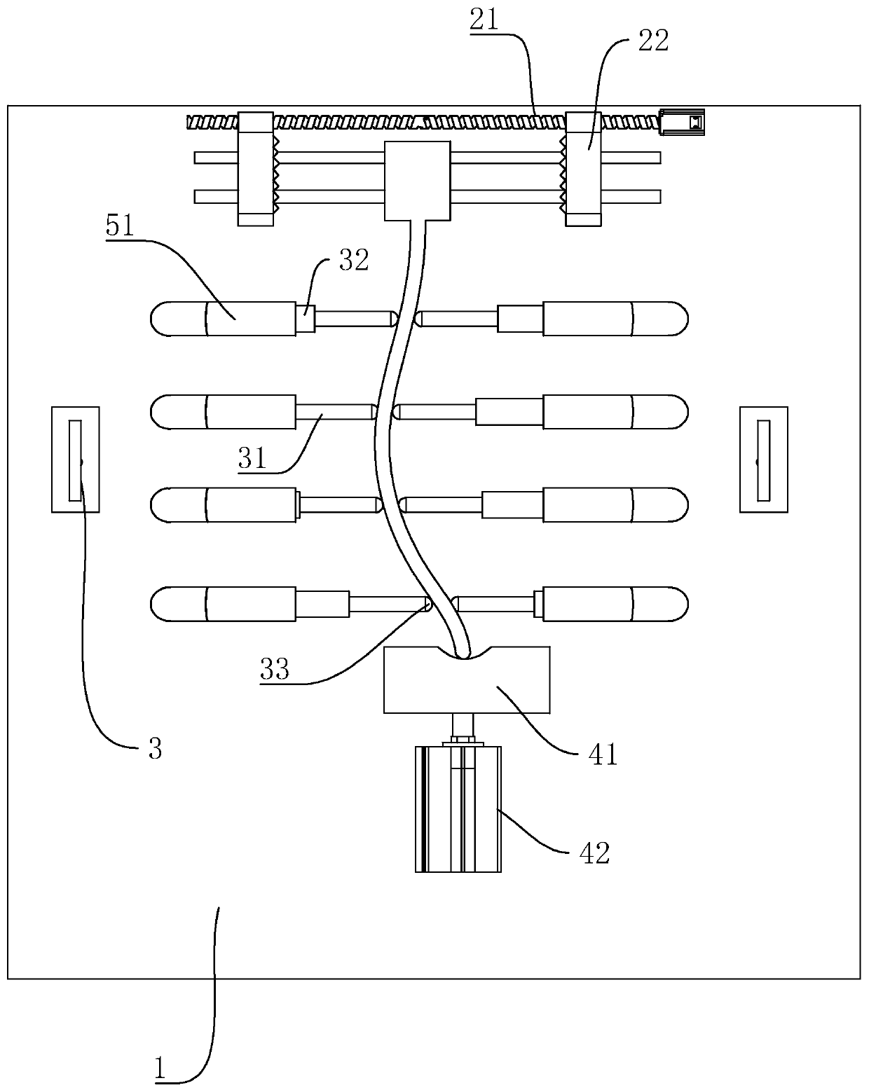
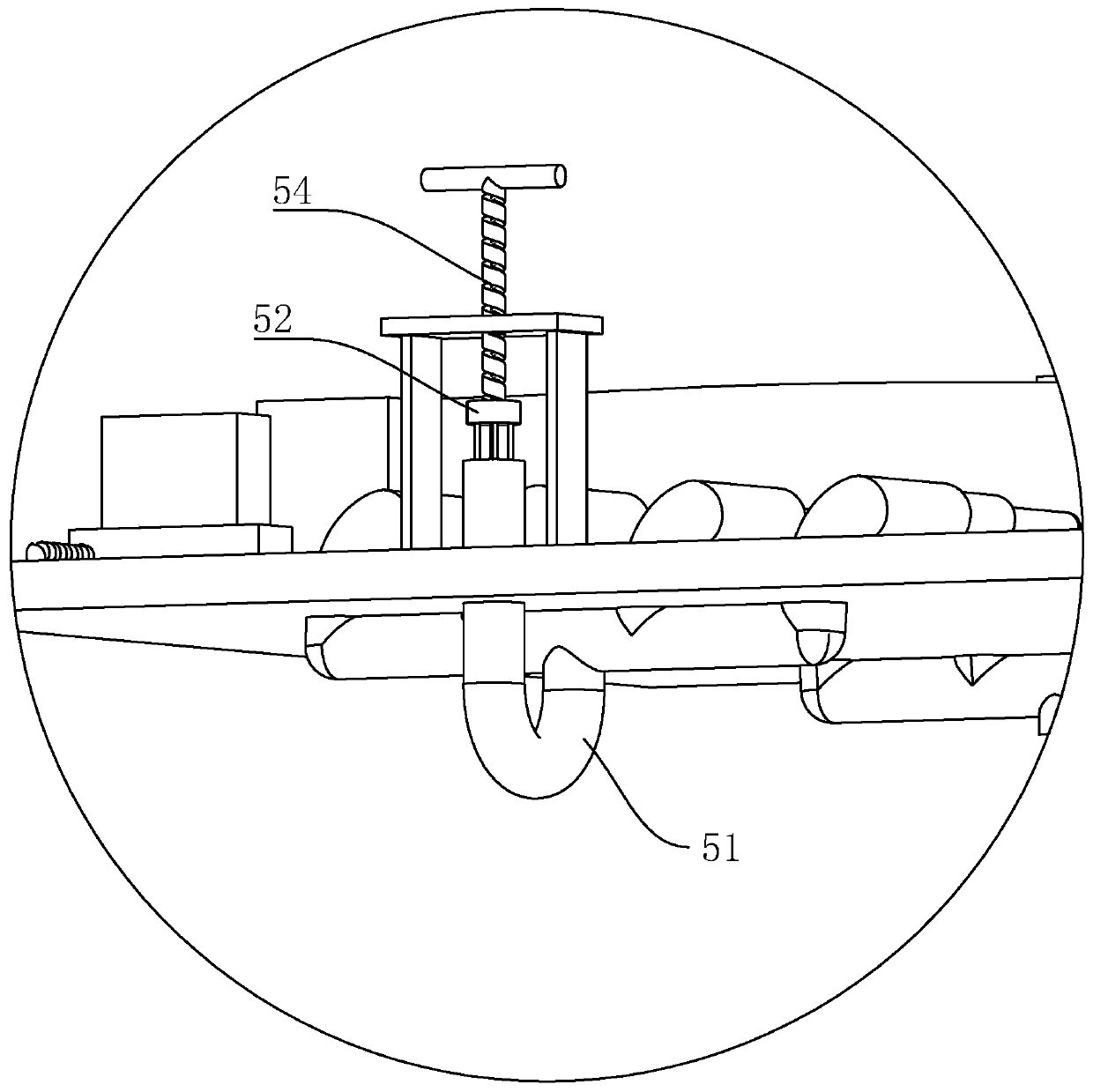
Steam turbine blade machining platform

A steam turbine blade and processing table technology, applied in metal processing equipment, manufacturing tools, grinding workpiece supports, etc., can solve problems such as complicated use, avoid frequent replacement, good overall positioning and support effect, and easy to use.

Pending Publication Date: 2019-07-26
南京赛达科技有限公司
View PDF9 Cites 5 Cited by
  • Summary
  • Abstract
  • Description
  • Claims
  • Application Information

AI Technical Summary

Problems solved by technology

[0007] However, when processing different types of steam turbine blades, due to their different radians and side curves, different blade positioning molds and corresponding fixtures need to be used. Therefore, operators need to frequently replace the positioning molds, which is more complicated to use

Method used


Image

  • Steam turbine blade machining platform
  • Steam turbine blade machining platform
  • Steam turbine blade machining platform

Examples


Embodiment 2

[0039] A kind of steam turbine blade processing table provided in this embodiment, such as Figure 4 As shown, the difference from Embodiment 1 is that the locking part 6 includes a pressurizing piston 52 slidably connected in the pressurizing tube, and a pushing rack 55 is fixed on the pressurizing piston 52, and the pushing rack 55 is compatible with the working The table 1 is slidingly connected, and a push gear 56 is connected to the workbench 1 through a rotating shaft 57 in rotation, and the push gear 56 and the push rack 55 are meshed with each other.

[0040]The locking part 6 includes a locking worm 62 coaxially fixed on the rotating shaft 57 and a locking worm 61 rotatably connected to the workbench 1. The locking worm 61 and the locking worm 62 are engaged with each other, and the workbench 1 There is a servo motor 63 for driving the locking worm 61 to rotate.

[0041] When the operator needs to process the blade, the top of the blade can be clamped and fixed by th...


PUM


Abstract

The invention discloses a steam turbine blade machining platform, and relates to the technical field of steam turbine parts. The steam turbine blade machining platform comprises a workbench. A first clamping part, a second clamping part and a third clamping part are arranged on the workbench in sequence. The first clamping part is used for fastening the top end of a blade. The second clamping partcan adapt to the shape of the blade and used for abutting against the middle section of the blade and tightly clamping the middle section of the blade from the two side faces. The third clamping partis connected to the workbench in a sliding mode and used for abutting against the bottom end of the blade. In the machining process, an operator does not need to replace a locating mechanism for theblade, after the blade is replaced, only the adaptive adjustment needs to be conducted, the different blades can be located and machined, and therefore the frequent replacement, conducted by the operator, of a locating mold is avoided, utilization is more convenient and easier, and the whole locating and supporting effect is better.

Description

technical field [0001] The invention relates to the technical field of steam turbine accessories, in particular to a steam turbine blade processing platform. Background technique [0002] The steam turbine, also known as the steam turbine engine, is a rotary steam power device. The high-temperature and high-pressure steam passes through the fixed nozzle to become an accelerated air flow and then sprays onto the blades, so that the rotor equipped with blade rows rotates and works externally. Steam turbines are the main equipment of modern thermal power plants, and are also used in metallurgical industry, chemical industry, and ship power plant. [0003] A steam turbine is an external combustion rotary machine that converts steam heat energy into mechanical work. After the steam from the boiler enters the steam turbine, it passes through a series of ring-shaped nozzles and moving blades in sequence to convert the thermal energy of the steam into the mechanical energy of the r...

Claims


Application Information

Patent Timeline
Patent Type & Authority Applications(China)
IPC IPC(8): B24B19/14B24B41/06
CPCB24B19/14B24B41/06
Inventor 刘达王河平宗国翼
Owner 南京赛达科技有限公司
Learn More