
Process for assembly of motor-generators

A technology for motor generators and armatures, which is used in the manufacture of motor generators, motor components, and the shape/style/structure of winding insulation, which can solve problems such as manual labor.

Active Publication Date: 2019-07-26
CHRISTOPHER W GABRIS +1
View PDF5 Cites 0 Cited by
  • Summary
  • Abstract
  • Description
  • Claims
  • Application Information

AI Technical Summary

Problems solved by technology

However, even for traditional electric generators, there is a lot of manual labor in the production process

Method used


Image

  • Process for assembly of motor-generators
  • Process for assembly of motor-generators
  • Process for assembly of motor-generators

Examples


Embodiment Construction

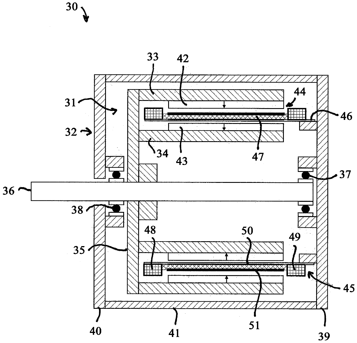
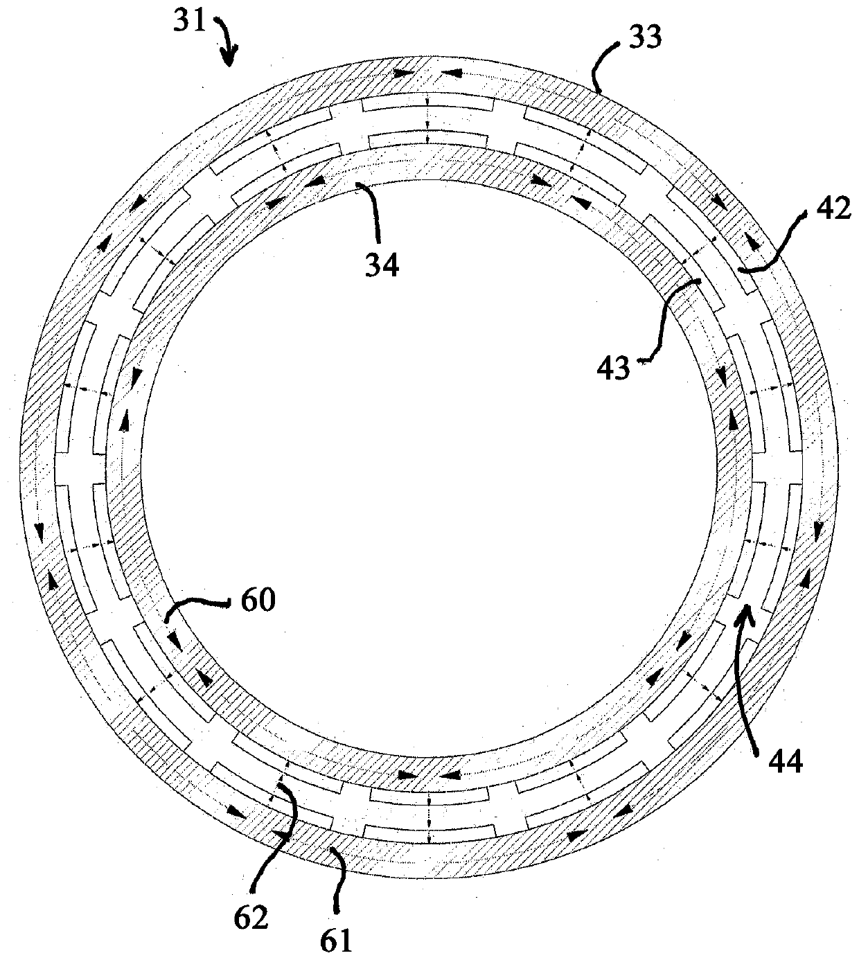
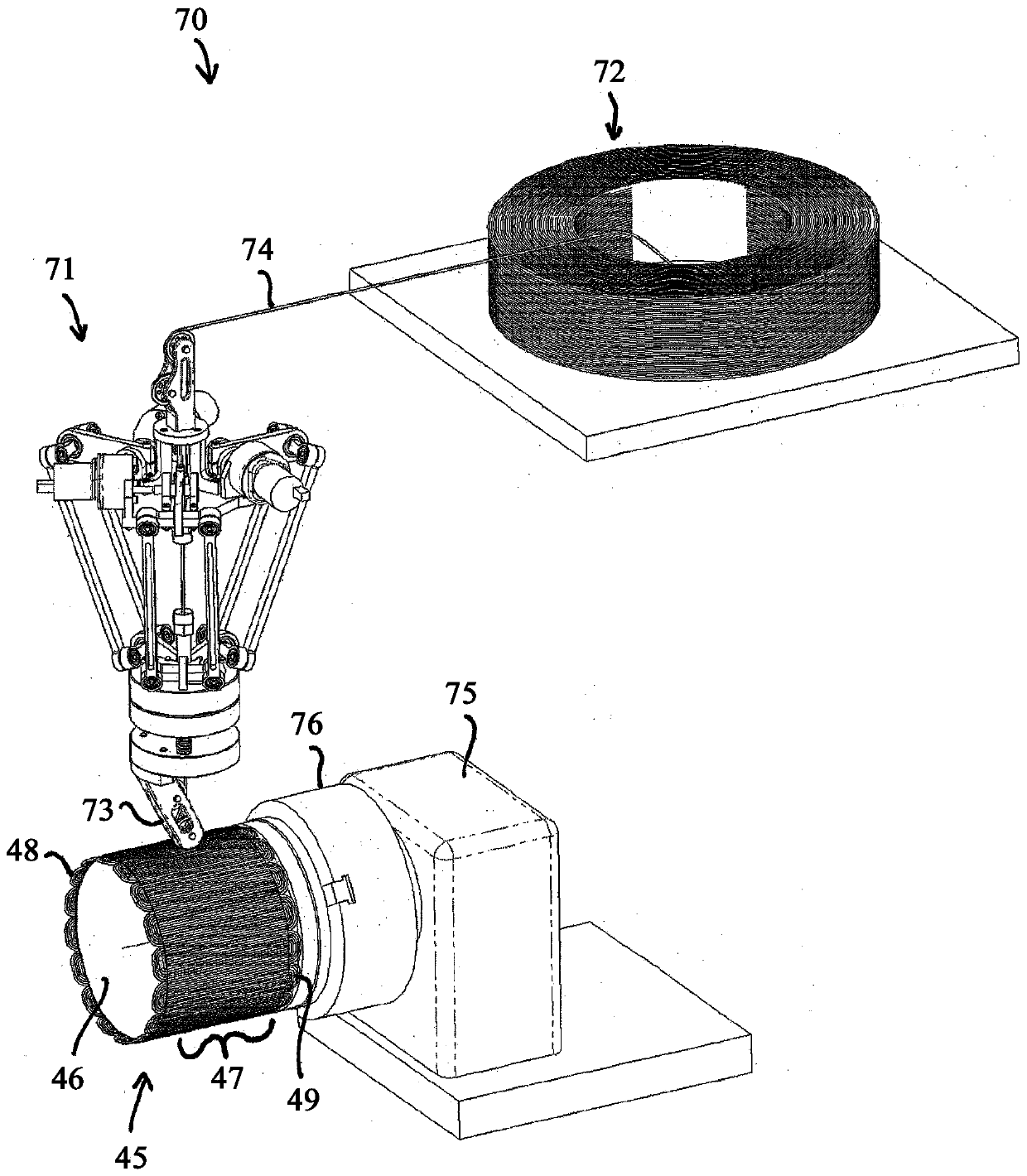
[0030] Turning to the drawings, wherein like reference numerals indicate like or corresponding parts, figure 1 A hollow core motor generator 30 comprising a rotor 31 and a stator 32 is shown. The rotor 31 consists of two concentrically spaced apart steel rotor columns 33 , 34 which are attached to a hub 35 . The hub 35 is supported by a central shaft 36 which is journaled for rotation by bearings 37 , 38 . Bearings 37 , 38 are mounted in housing end plates 39 , 40 which are connected together by an outer housing tube 41 . Attached to the rotor tubes 33, 34 are circumferential alternating polarity permanent magnet arrays 42, 43 which drive magnetic flux back and forth between the rotor tubes 33, 34 and an armature gap 44 formed between the rotor tubes. Positioned within the armature void 44 is a hollow armature 45 which is attached to the stationary housing end plate 39 . The hollow armature 45 consists of a non-magnetic form tube 46 that extends into the armature void 44 an...


PUM


Abstract

A process for assembling a brushless motor-generator includes assembling a rotor formed from two spaced apart rotor portions having magnetic poles that drive magnetic flux circumferentially through the rotor portions and back and forth across an armature airgap formed between the rotor portions. An air core armature is formed by coating a substantially nonmagnetic armature form with a tacky adhesive layer, and winding armature windings into a winding pattern onto the substantially nonmagnetic form using wire made of multiple individually insulated conductor strands that are electrically connected in parallel but are electrically insulated from each other along their length when located inside the armature airgap, wherein the strands of said wire are diametrically held together by an outerserve. The winding of the armature form includes sequentially applying pressure to sections of said wire against the tacky adhesive layer.

Description

[0001] The present invention relates to electromechanical generators for conversion between electrical and mechanical energy, and more particularly, to a new method for assembling electromechanical generators resulting in high electromechanical energy conversion efficiency and power density. This unique approach currently enables the manufacture of these machines at higher speeds while being highly automated. Background technique [0002] A motor-generator converts between electrical power and rotating mechanical power. Electric motors typically consume more than 50% of the electrical power generated. In order to save energy and reduce pollution to the environment, there is a great desire to improve the efficiency of electric motors. [0003] The efficiency of the motor generator can potentially be improved by reducing resistive and magnetic induction losses. Magnetic losses include both hysteresis and eddy current losses and are the result of changing magnetic fields throug...

Claims


Application Information

Patent Timeline
Patent Type & Authority Applications(China)
IPC IPC(8): H02K15/08H02K1/06
CPCH02K1/06H02K3/30H02K3/32H02K15/0435H02K15/08H02K3/47H02K15/02Y10T29/49012
Inventor 克里斯托弗·W·加布里斯蒂莫西·S·罗杰斯
Owner CHRISTOPHER W GABRIS
Features
  • Generate Ideas
  • Intellectual Property
  • Life Sciences
  • Materials
  • Tech Scout
  • Unparalleled Data Quality
  • Higher Quality Content
  • 60% Fewer Hallucinations
Learn More