Spinning system

A spinning and spinning machine technology, applied in the field of pipe processing equipment, can solve the problems of low degree of automation, high processing efficiency and cost, low production efficiency, etc., and achieve the effect of simplifying the structure, improving the speed and the degree of automation

Pending Publication Date: 2019-07-30
浙江长兴和良智能装备有限公司
View PDF2 Cites 3 Cited by
  • Summary
  • Abstract
  • Description
  • Claims
  • Application Information

AI Technical Summary

Problems solved by technology

In the whole production process, there are problems such as high labor cost, low degree of automation, and low production efficiency due to the high cost of labor and time-consuming.
[0005] In addition,

Method used


Image

  • Spinning system
  • Spinning system
  • Spinning system

Examples


Embodiment 1

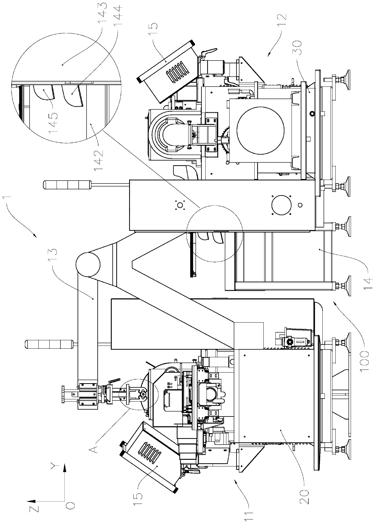
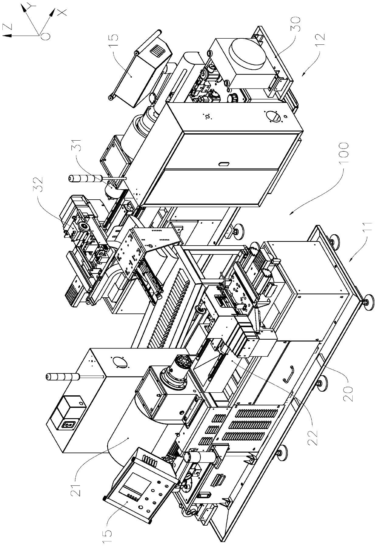
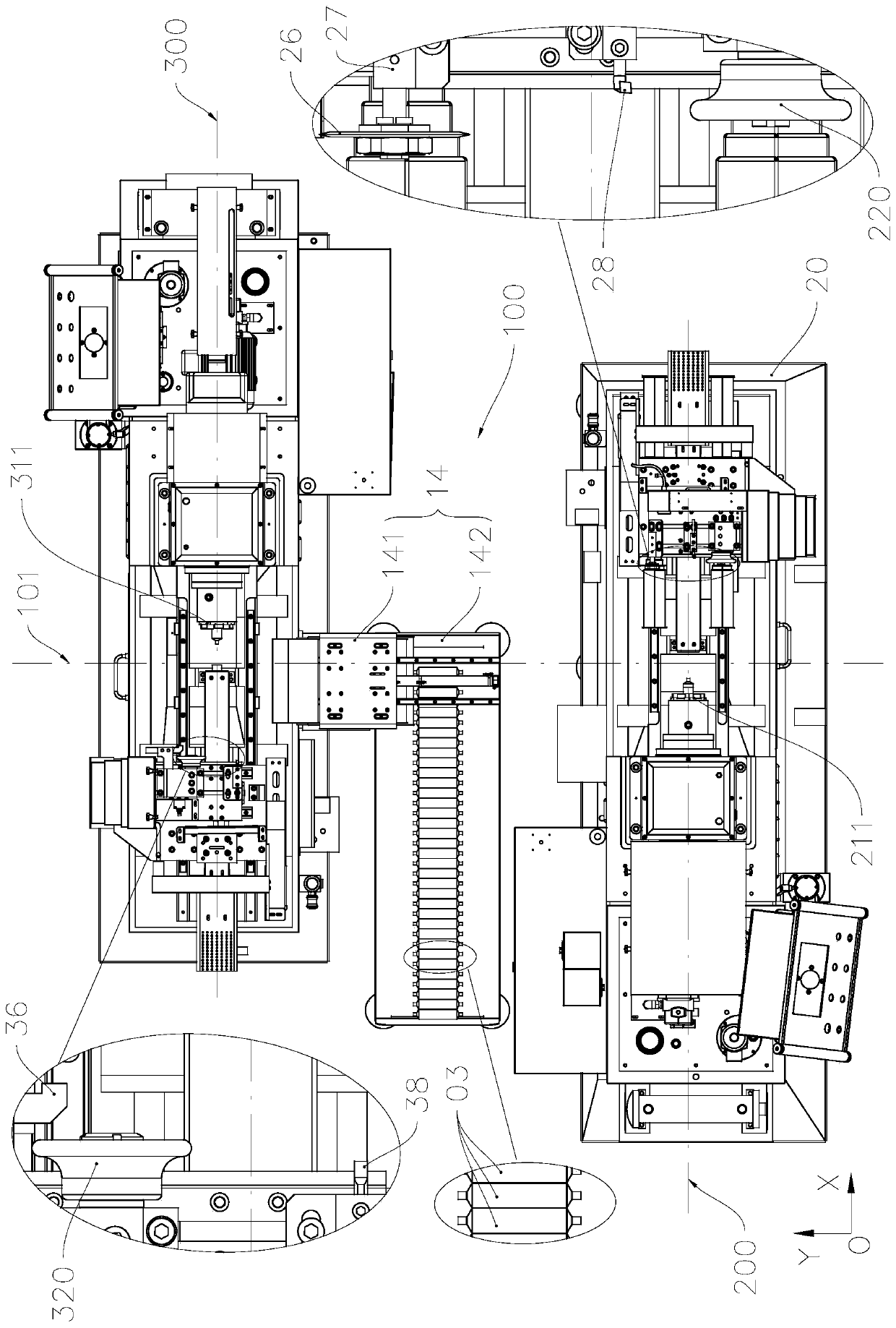
[0061] see Figure 1 to Figure 4 and Figure 14 The spinning system 1 of the present invention includes a control device and a feeding device 10 controlled by the control device, a first spinning machine 11, a second spinning machine 12, a swing moving system 13 and an unloading system 14. The material system 13 is used to transfer the tube material that has undergone tube end treatment such as spinning by the first spinning machine 11 to the second spinning machine 12 for re-spinning and other tube end treatment. In this embodiment, the pipe end treatment includes spinning, flat pipe end, inner hole, internal and external chamfering of the end surface, etc.

[0062] The control device includes a touch control panel 15, a processor and a memory, and the memory stores computer programs; the touch control panel 15 receives the operator's control instructions, so that the processor executes the corresponding computer program stored in the memory to control each functional unit ...

Embodiment 2

[0109] As a description of Embodiment 2 of the present invention, only the differences from Embodiment 1 above will be described below.

[0110] Such as Figure 18 As shown, in the swing manipulator 5, its installation base 50 is installed on the lifting output end of the lifting drive mechanism 81, so as to omit the telescopic actuator installed on the swing end of the swing arm 51, but the swing actuator Still reserved, at this time, the distance between the pipe clamp 73 and the swing end of the swing arm 51 can be increased by using the extension rod, thereby using the lifting drive mechanism 81 to drive the pipe clamp 73 to move closer to or away from the current clamping area from the pipe end processing avoidance area claw.

[0111] In addition, the installation base 50 can also be installed on the traversing driving mechanism 82 to adjust the position of the pipe clamp 73 in the Y-axis direction.

Embodiment 3

[0113] As an explanation of Embodiment 3 of the present invention, only the differences from Embodiment 1 above will be described below.

[0114] Such as Figure 19 As shown, the swing arm 51 swings around the vertical axis relative to the installation base 50. The vertical axis is arranged along the Z axis, that is, arranged vertically, and the swing actuator is omitted. At this time, the first spinning machine 11 and the second spinning machine 12 are arranged side by side in the same direction, that is, on both, the direction from the clamping jaw to the extruded part is in the same direction.

[0115] Such as Figure 20 As shown, in the swinging manipulator 5, its mounting base 50 is installed on the lifting output end of the lifting drive mechanism 81, so as to omit the telescopic actuator installed on the swinging end of the swinging arm 51, at this time, you can use The extension bar increases the distance between the pipe clamp 73 and the swing end of the swing arm 5...


PUM


Abstract

The invention relates to a spinning system, and belongs to the technical field of pipe processing. The spinning system comprises a first spinning machine, a second spinning machine and a swing transferring system; the first spinning machine comprises a first clamping jaw; the second spinning machine comprises a second clamping jaw; the swing transferring system comprises a mounting base, a swing arm, a swing driving device, a pushing device and a pipe clamping unit arranged on the swing end of the swing arm; the swing driving device is used for driving the swing arm to swing relative to the mounting base, so that the swinging end can swing from a first position to a second position, in the first position, the pipe clamping unit can be used for discharging a pipe from the first clamping jaw, and in the second position, the pipe clamping unit can be coordinated with the pushing device for feeding the second clamping jaw; and the pushing device is used for pushing the pipe clamped on thepipe clamping unit to the second clamping claw. According to the spinning system, the pipe can be automatically conveyed between the two spinning machines so as to carry out repeated spinning processing, and the spinning system is high in automation degree, capable of saving manufacturing cost and capable of being widely applied to the fields of refrigeration, automobiles, aviation and the like.

Description

technical field [0001] The invention relates to pipe processing equipment, in particular to a spinning system composed of a plurality of spinning machines. Background technique [0002] In the field of production parts, the spinning machine is usually used to spin the pipe end to form rotating parts with different structures on the pipe end, for example, spinning out the end compression structure to produce a liquid storage tank , Muffler and other tubular parts. [0003] Structurally, the spinning machine usually includes clamping claws and extrusion parts that are relatively rotated under the drive of the rotary drive equipment. Among them, the extrusion parts can adopt a wheel structure or a ball structure. For the ball structure, the common structure has a single claw Spinning machine or three-jaw spinning machine; for the wheel structure, there are two main structures, namely: (1) The rotating drive device drives the clamping jaws to rotate through the rotating drive s...

Claims


Application Information

Patent Timeline
IPC IPC(8): B21D22/14B21D43/10
CPCB21D22/14B21D43/006B21D43/10
Inventor 赖如福李良有周协恒金腾
Owner 浙江长兴和良智能装备有限公司
Why Eureka
Try Eureka