Concrete composite slab mold
A technology of laminated slabs and concrete, applied in molds, mold auxiliary parts, manufacturing tools, etc., can solve the problems of uncontrollable quality, cumbersome operation, heavy workload, etc., and achieve the effect of simple structure, no pollution to the environment, and convenient operation
- Summary
- Abstract
- Description
- Claims
- Application Information
AI Technical Summary
Problems solved by technology
Method used
Image

Examples
Embodiment 1
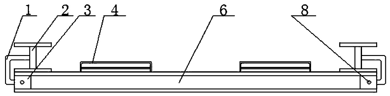
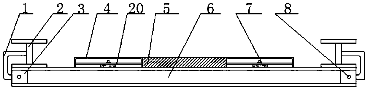
[0033] Please refer to figure 1 , figure 2 , image 3 , Figure 4 , Figure 5 and Figure 10 , a concrete laminated slab mould, the mold comprises a base form 6, support plates 2 are arranged on both sides of the base form, a plurality of side forms 4 are arranged between the support plates, and the side forms are provided with Reinforcement holes 19, the side form is arranged on the bottom form.
[0034] As a further optimization of this scheme, the support plate is connected to the bottom mold through a U-shaped plate 1, one end of the U-shaped plate is connected to the support plate, and the other end is provided with a first through hole (not shown in the figure), the A splint 3 is provided in the bottom mold, and a second through hole 8 is arranged on the splint. The other end of the U-shaped plate is placed in the splint, and the first through hole and the second through hole are matched by a pin shaft so that the U-shaped Plate and bottom mold connection.
[003...
Embodiment 2
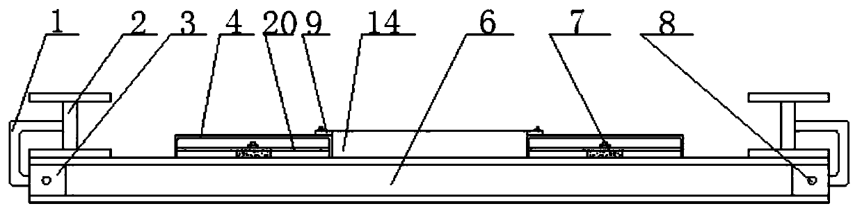
[0043] Please refer to figure 1 , Figure 6 , Figure 7 , Figure 8 , Figure 9 and Figure 10 , a concrete laminated slab mould, the mold includes a base form, support plates are provided on both sides of the base form, a plurality of side forms are provided between the support plates, and steel bar holes are provided on the side forms, The side mold is arranged on the bottom mold.
[0044] As a further optimization of this scheme, the support plate is connected to the bottom mold through a U-shaped plate, one end of the U-shaped plate is connected to the support plate, and the other end is provided with a first through hole, and a splint is provided in the bottom mold, so The splint is provided with a second through hole, the other end of the U-shaped plate is placed in the splint, and the first through hole is matched with the second through hole through a pin to connect the U-shaped plate to the bottom mold.
[0045] As a further optimization of this scheme, the side...
PUM
 Abstract
Description
Claims
Application Information
 - R&D
- Intellectual Property
- Life Sciences
- Materials
- Tech Scout
- Unparalleled Data Quality
- Higher Quality Content
- 60% Fewer Hallucinations
Browse by: Latest US Patents, China's latest patents, Technical Efficacy Thesaurus, Application Domain, Technology Topic, Popular Technical Reports.
© 2025 PatSnap. All rights reserved.Legal|Privacy policy|Modern Slavery Act Transparency Statement|Sitemap|About US| Contact US: help@patsnap.com