Water tank mounting structure of motorcycle engine

An installation structure and engine technology, applied in the cooling of the engine, engine components, machine/engine, etc., can solve the problems of low heat dissipation efficiency of the water tank, achieve good ventilation effect, avoid scalding the driver, and improve the effect of heat dissipation

Pending Publication Date: 2019-07-30
浙江美可达摩托车有限公司
1 Cites 0 Cited by

AI-Extracted Technical Summary

Problems solved by technology

[0004] The purpose of the present invention is to solve the problem of low cooling efficiency of the water tank of the existing motorcycle engin...

Abstract

The invention provides a water tank mounting structure of a motorcycle engine, and belongs to the technical field of motorcycles. The problem that the heat radiation efficiency of a water tank of an existing motorcycle engine is low is solved. According to the water tank mounting structure of the motorcycle engine, the engine comprises a cylinder body; a fan is arranged on the cylinder body; the mounting structure comprises a plate-shaped support fixed to the cylinder body; a ventilation hole opposite to the fan is formed in the support; a water tank is fixed to the outer side face of the support and is opposite to the ventilation hole; two parallel sealing grooves are formed in the outer side face of the support; two parallel sealing flanges are further arranged on the outer side face ofthe support; the two sealing grooves and the two sealing flanges define a rectangle; the two ends of the water tank are provided with sealing convex edges, and the two sealing convex edges are embedded into the two sealing grooves to for sealing; and the two sealing flanges are opposite to the two sides of the water tank correspondingly, and sealing is formed. The heat radiation efficiency of thewater tank of the motorcycle engine is higher.

Application Domain

Cylinder headsCylinders +2

Technology Topic

Agricultural engineeringCylinder block +4

Image

  • Water tank mounting structure of motorcycle engine
  • Water tank mounting structure of motorcycle engine
  • Water tank mounting structure of motorcycle engine

Examples

  • Experimental program(1)

Example Embodiment

[0029] The following are specific embodiments of the present invention and the accompanying drawings to further describe the technical solutions of the present invention, but the present invention is not limited to these embodiments.
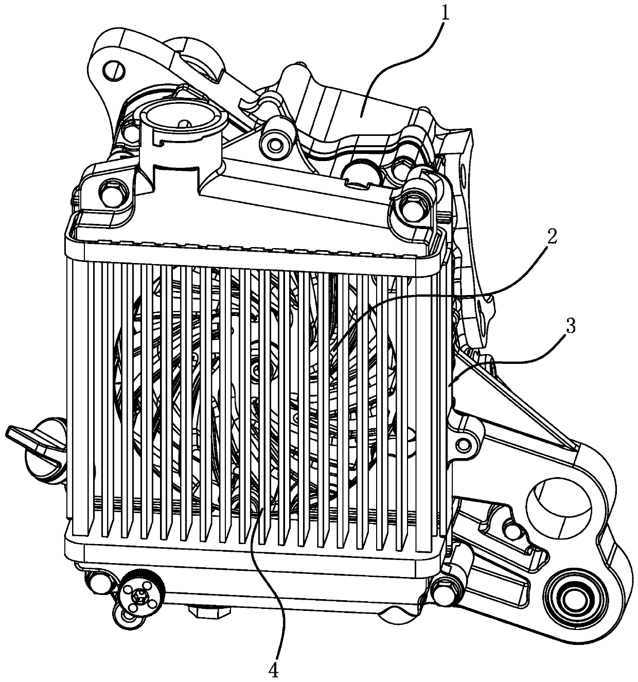
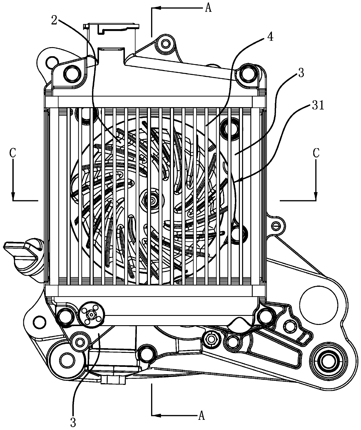
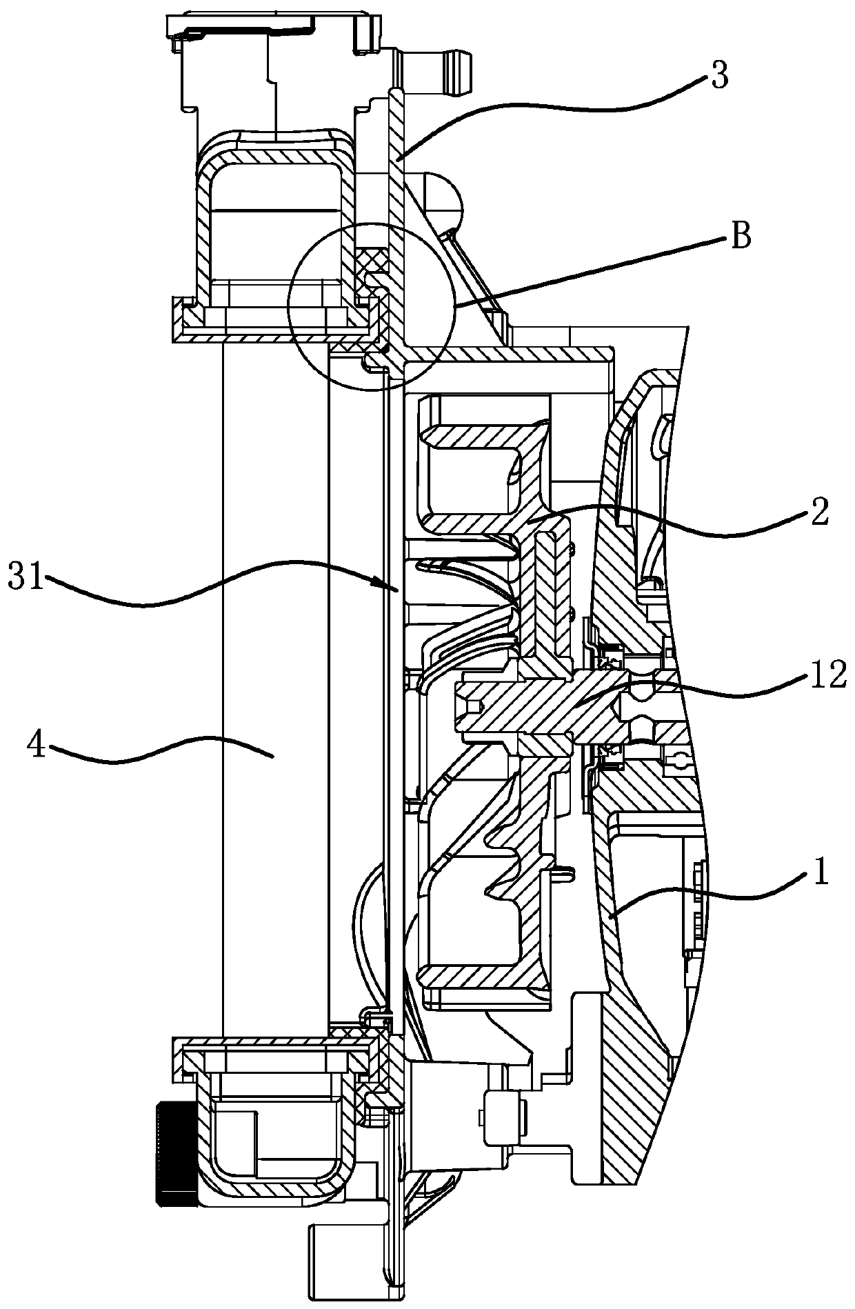
[0030] like figure 1 , figure 2 , image 3 As shown, a water tank 4 installation structure for a motorcycle engine, the engine includes a cylinder block 1, a crankshaft 12 is arranged in the cylinder block 1, one end of the crankshaft 12 protrudes from the cylinder block 1, and the protruding end of the crankshaft 12 is The fan 2 is fixed, and the installation structure includes a bracket 3 fixed on the cylinder block 1. The bracket 3 is in the shape of a rectangular plate, and the fan 2 is located inside the bracket 3, that is, the fan 2 is located between the bracket 3 and the cylinder block 1. A ventilation hole 31 is opened in the middle, and the fan 2 is opposite to the ventilation hole 31. The outer diameter of the fan 2 is slightly smaller than the aperture of the ventilation hole 31. A water tank 4 is fixed on the outer surface of the bracket 3. 4 is opposite to the ventilation hole 31 . combine Figure 4 As shown, there are a pair of sealing ribs 32 along the length direction at the opposite two edges of the outer side of the bracket 3, and a sealing groove 33 is formed between the two sealing ribs 32 of the same pair, and the two sealing grooves 33 are arranged in parallel. 3. There are also two parallel sealing flanges 34 on the outer side. The sealing flanges 34 are perpendicular to the outer side of the bracket 3. The two sealing grooves 33 and the two sealing flanges 34 are perpendicular to each other and form a rectangle. The two ends of the inner sealing rib 32 of the rib 32 respectively extend to butt joint with the ends of the two sealing flanges 34, and are combined with each other. Figure 5 , Image 6 As shown, the sealing groove 33 is filled with the sponge 5, and the inner side edges of both ends of the water tank 4 have sealing protruding edges 41 along the length direction. The water tank 4 is located between the two sealing flanges 34, and the two side edges of the water tank 4 are respectively opposite to the two sealing flanges 34. The sponge 5 is filled between the edge of the water tank 4 and the sealing flanges 34, and the inner side of the water tank 4 is opposite to the two sealing flanges 34. There is a gap between the outer sides of the bracket 3 , and a sponge 5 is filled between the inner side of the water tank 4 and the outer side of the bracket 3 .
[0031] The cylinder block 1 is provided with a number of support columns 11, and the inner side of the bracket 3 is vertically provided with a number of connection columns 35. The connection columns 35 are respectively connected with the support columns 11 one by one, and are connected through bolts, and the support columns 11 are connected to the connection columns. 35 supports so that there is space between the bracket 3 and the cylinder block 1, combined with Figure 7 As shown, there are several front guide fins 36 and several rear guide fins 37 vertically on the inner side of the bracket 3, the several front guide fins 36 are located on the front side of the fan 2, the several front guide fins 36 are arranged in parallel, and A front guide channel 361 is formed between two adjacent front guide plates 36 , and the front end of the front guide channel 361 is inclined downward. A plurality of rear guide fins 37 are located on the rear side of the fan 2 , and the plurality of rear guide fins 37 are arranged in parallel, and a rear guide channel 371 is formed between two adjacent rear guide fins 37 , and the rear end of the rear guide channel 371 is formed. The horizontal arrangement is rearward, and then the guide channel 371 can also be slightly inclined. The rear side of the bracket 3 is also vertically provided with a long baffle 38. The baffle 38 is located on the upper side of the fan 2. The baffle 38 is arc-shaped, and the baffle 38 is arranged along the upper edge of the ventilation hole 31. The front end of the baffle 38 is in contact with the rear end of the uppermost front guide fin 36, and the front end of the baffle 38 and the rear end of the front guide fin 36 smoothly transition, and the rear end of the baffle 38 is located above the uppermost rear guide fin 37 .
[0032] The specific embodiments described herein are merely illustrative of the spirit of the invention. Those skilled in the art to which the present invention pertains can make various modifications or additions to the described specific embodiments or substitute in similar manners, but will not deviate from the spirit of the present invention or go beyond the definitions of the appended claims range.
[0033] Although the terms such as the cylinder block 1, the support column 11, the crankshaft 12, etc. are often used herein, the possibility of using other terms is not excluded. These terms are used only to more conveniently describe and explain the nature of the present invention; it is contrary to the spirit of the present invention to interpret them as any kind of additional limitation.

PUM

no PUM

Description & Claims & Application Information

We can also present the details of the Description, Claims and Application information to help users get a comprehensive understanding of the technical details of the patent, such as background art, summary of invention, brief description of drawings, description of embodiments, and other original content. On the other hand, users can also determine the specific scope of protection of the technology through the list of claims; as well as understand the changes in the life cycle of the technology with the presentation of the patent timeline. Login to view more.

Similar technology patents

Air film cooling hole structure

ActiveCN106640216AImprove cooling efficiencyIncrease the export area
Owner:HEBEI UNIV OF TECH

High definition camera

Owner:南京拓慧自动化技术有限公司

Fixing structure of radiator

InactiveCN101754639Areduce product heightImprove cooling efficiency
Owner:DELTA ELECTRONICS INC

Brake cooling method and brake cooling device

InactiveCN104859606AImprove cooling efficiencyavoid slippery roads
Owner:WEICHAI POWER CO LTD

Classification and recommendation of technical efficacy words

  • Improve the sealing effect
  • Improve cooling efficiency

Water plugging device for petroleum pipeline maintenance

Owner:JIANGSU PROVINCE JINFENG PETROLEUM MACHINERY MFG CO LTD

Method for sintering polytetrafluoroethylene

Owner:广东新志密封技术有限公司

Brake pump piston ring of car air compressor

InactiveCN103790803AImprove the sealing effectreduce lower exhaust
Owner:NANJING FAYN PISTON RING

Method and device for controlling inverter compressor

InactiveCN101539151AImprove cooling efficiencyavoid overshoot
Owner:HAIER GRP CORP +1

Data center and cooling system thereof

Owner:HONGFUJIN PRECISION ELECTRONICS (TIANJIN) CO LTD

Process for preparing size-controllable nano-silicon dioxide

InactiveCN1546373AImprove cooling efficiencyprevent particle size increase
Owner:GUANGZHOU GBS HIGH TECH & IND
Why Eureka
Try Eureka