Sliding plate supported type non-through shaft plunger pump or motor

A plunger pump, supported technology, applied in the field of sliding plate supported non-through-shaft plunger pump or motor, to achieve the effect of reducing the cost of use, less maintenance in the later period, and simplifying the structure

Pending Publication Date: 2019-07-30
钟彪
View PDF0 Cites 5 Cited by
  • Summary
  • Abstract
  • Description
  • Claims
  • Application Information

AI Technical Summary

Problems solved by technology

[0005] The purpose of the present invention is to provide a non-through-shaft axial piston pump or motor structure for the current problems of the existing sliding shoe type swash plate axial piston pump or motor, which aims to reduce the friction of the friction pair. Quantity, reduce the impact of the overturning of the cylinder caused by the lateral force of the plunger, reduce the structural size, simplify the structure of the return mechanism, thereby improving the working reliability, volumetric efficiency, and working life of the swash plate axial piston pump or motor.

Method used


Image

  • Sliding plate supported type non-through shaft plunger pump or motor
  • Sliding plate supported type non-through shaft plunger pump or motor
  • Sliding plate supported type non-through shaft plunger pump or motor

Examples


Embodiment 1

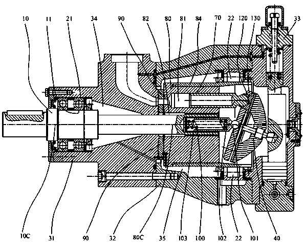
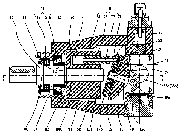
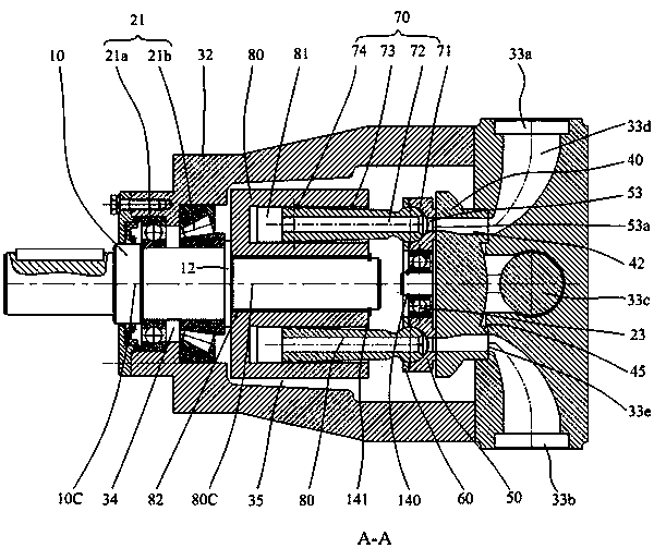
[0043] like Figure 2-9 Shown is an embodiment of the sliding plate supported non-through shaft plunger pump of the present invention. In the preferred embodiment shown, the axial plunger pump includes a main shaft 10, a housing, a first bearing 21, a bevel Disc 40, sliding plate 50, plunger 70 and cylinder 80, the spindle axis 10C of the said main shaft 10 coincides with the cylinder central axis 80C of said cylinder 80, one end of said main shaft 10 protrudes out of the housing and supports On the first bearing 21, the other end of the main shaft 10 cantilever supports the cylinder body and is connected with the cylinder body 80 through a key. The sliding plate 50 is supported on the swash plate 40 and is closely matched with the working surface of the swash plate 40. One end of the sliding plate 50 is provided with a plurality of waist-shaped oil chambers 53a, and the other end surface of the sliding plate 50 is provided with a plurality of plunger ball sockets 58, and the ...

Embodiment 2

[0067] like Figure 10 As shown, the main difference from Embodiment 1 is that a flow distribution plate 90 is interposed between the sliding plate 50 and the swash plate 40 in the sliding plate pair, and the static pressure bearing surface 51 is supported on the flow distribution plate 90 and is connected with the flow distribution plate 90 Keeping the sliding fit, the distribution plate is fixed on the swash plate by means of pins, etc., and the distribution plate 90 is provided with a high-pressure distribution port 93 and a low-pressure distribution port 92, such as Figure 11 As shown, the high-pressure distribution port 93 and the low-pressure distribution port 92 communicate with the low-pressure distribution window 43 and the high-pressure distribution window 44 on the swash plate respectively. The low-pressure distribution port 92 and the high-pressure distribution port 93 can be arranged in a symmetrical or asymmetrical structure relative to the central plane, for ex...

Embodiment 3

[0070] like Figure 12 and 13 As shown, the main difference from other embodiments is that the sliding plate of the sliding plate supported non-through-shaft plunger pump or motor adopts an external support method, and the outer peripheral portion of the swash plate is provided with a support stop portion 41a, and the sliding plate 50 A third bearing 23 is interposed between the outer side and the inner side of the support stop portion 41a, and the sliding plate 50 is supported on the third bearing 23 in a radially constrained state. When the main shaft 10 and the cylinder body 80 are rotating, The plunger 70 reciprocates in the plunger cavity of the cylinder body 80 to realize oil suction and discharge of the pump or motor.

[0071] Likewise, the return structure of the axial piston pump or motor includes a restricting device on one side of the flow distribution sliding plate pair, and the restricting device restricts the sliding plate 50 away from the end surface of the swa...


PUM


Abstract

The invention discloses a sliding plate supported type non-through shaft plunger pump or motor. The sliding plate supported type non-through shaft plunger pump or motor comprises a spindle, a cylinderbody, a swash plate and a sliding plate, wherein the cylinder body and the spindle rotate synchronously; the sliding plate is supported on the swash plate; a cantilever at the end part of the spindle is used for supporting the cylinder body and is connected with the cylinder body through a key; the sliding plate is of an integrated structure; the end face, opposite to the swash plate, of the sliding plate is provided with a hydrostatic supporting surface; the hydrostatic supporting surface is provided with a plurality of oil chambers; the other end face of the sliding plate is provided witha plurality of plunger ball sockets; the sliding plate is provided with a large-hole-diameter oil passing hole which communicates with the plunger ball sockets and the oil chambers; the swash plate isprovided with a flow distributing oil tank which communicates with an oil inlet and an oil outlet; a third bearing is arranged between the sliding plate and the swash plate; and the sliding plate issupported on the third bearing in a manner of being restrained in the radial direction of the sliding plate. The sliding plate supported type non-through shaft plunger pump or motor disclosed by the invention improves the performances such as work reliability, volume efficiency and working life of a swash plate type axial plunger pump or motor.

Description

technical field [0001] The invention belongs to the technical field of hydraulic transmission and control, and relates to a swash plate type axial plunger pump or motor, in particular to a sliding plate support type non-through shaft plunger pump or motor. Background technique [0002] Axial piston pumps and motors are one of the most widely used hydraulic components in modern hydraulic transmission, among which hingeless inclined axis pumps and sliding shoe swash plate axial piston pumps are currently the most widely used and most important two. Axial piston pumps. Inclined shaft pumps and sliding shoe swash plate types also have their own characteristics. These two pumps or motors are still competing at present, and each is constantly improving and developing. [0003] like figure 1 As shown, it is a typical structure of a non-through-shaft swash plate axial piston pump or motor, including a swash plate 40, a sliding shoe 120, a plunger 70, a cylinder block 80, a flow pl...

Claims


Application Information

Patent Timeline
Patent Type & Authority Applications(China)
IPC IPC(8): F04B1/22F04B53/00F04B53/14F04B53/16F03C1/253F03C1/28F03C1/32
CPCF03C1/0605F03C1/0639F03C1/0644F03C1/0663F03C1/0668F03C1/0671F04B1/124F04B1/2014F04B1/2064F04B1/2078F04B1/2085F04B1/22
Inventor 钟彪
Owner 钟彪
Why Eureka
Try Eureka