A dual-coil current sensor

A current sensor, double coil technology, applied in the direction of only measuring current, measuring current/voltage, components of electrical measuring instruments, etc., can solve the problems of incorrect non-sine wave measurement, prone to fire, and accelerating the aging speed of the device. , to avoid high temperature accelerated aging and easy fire, reduce safety hazards, and slow down the aging speed.

Inactive Publication Date: 2021-03-23
YANTAI ENG & TECH COLLEGE YANTAI TECHNICIAN INST
View PDF7 Cites 0 Cited by
  • Summary
  • Abstract
  • Description
  • Claims
  • Application Information

AI Technical Summary

Problems solved by technology

[0003] However, traditional current sensors have problems such as large heat generation, high cost, incorrect measurement of non-sine waves, low measurement accuracy, and large temperature changes. Therefore, people propose a dual-coil current sensor, as disclosed in Chinese patent CN201749142U One of them includes coils and measuring wires, two identical coils are arranged, and the two identical coils are arranged in the same plane, and the measuring wires are arranged on the symmetrical line of the two coils
Since the coil is an air-core coil, the mechanism is small in size, and the measured current wire is placed between the two coils. When there is interference from the outside world, the magnetic force lines passing through the two coils are in the same phase, and the voltage at the output terminal is a common-mode voltage. The output voltage is The difference between the induced voltages of the two coils minimizes the interference, but in actual use, as the ambient temperature changes, the temperature of the inner wall of the sensor will also be affected by interference, especially in high-temperature environments. Accelerate the aging speed of the device, and accidents such as fire are prone to occur, which brings safety hazards to the use

Method used


Image

  • A dual-coil current sensor
  • A dual-coil current sensor

Examples


Embodiment Construction

[0020] The following will clearly and completely describe the technical solutions in the embodiments of the present invention with reference to the accompanying drawings in the embodiments of the present invention. Obviously, the described embodiments are only some, not all, embodiments of the present invention. Based on the embodiments of the present invention, all other embodiments obtained by persons of ordinary skill in the art without making creative efforts belong to the protection scope of the present invention.

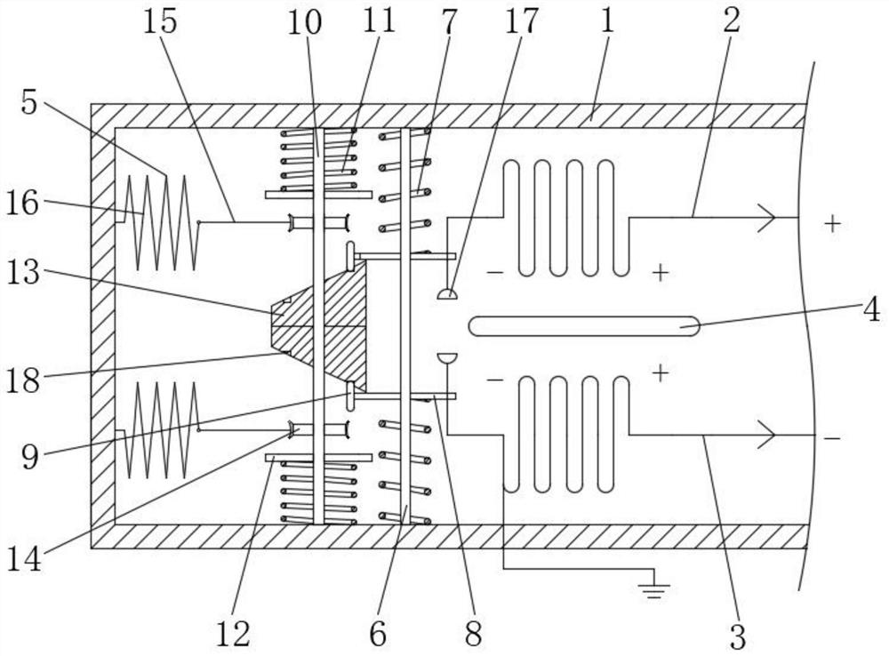
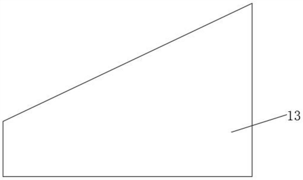
[0021] see Figure 1 to Figure 2 , the present invention provides a technical solution: a double-coil current sensor, including a housing 1, a coil 2, a coil 2 3 and a measuring wire 4, the coil 1 2 and the coil 2 3 have the same size and are inside the housing 1 Symmetrically arranged, when the current flows through the measuring wire 4, a magnetic field is generated, the magnetic force line passes through the coil one 2 and the coil two 3, and a voltage is i...


PUM


Abstract

The invention discloses a double coil current sensor comprising a casing, a first coil, a second coil and a measuring wire, wherein the first coil and the second coil share the same size and are symmetrically arranged in the casing, the measuring wire is arranged on the horizontal center line of the first coil and the second coil, the positive end of the first coil is connected to the positive endof the output, the positive end of the second coil is connected to the negative end of the output, the negative ends of the first coil and the second coil are connected with each other and further connected to a ground end, the inner wall of the casing is fixedly connected with a cooling mechanism comprising a first rod, and compression springs are sleeved on the surfaces of the first rod near both ends. The double coil current sensor provided by the invention solves the problem of a safety hazard to use due to unexpected situations such as the temperature of the inner wall of the sensor is also disturbed to change due to the change of the ambient temperature during the actual use, especially in the high-temperature use environment, the aging speed of the device is accelerated, and the fire is prone to occur.

Description

technical field [0001] The invention relates to the technical field of current measurement, in particular to a double-coil current sensor. Background technique [0002] The current sensor is a detection device that can sense the information of the measured current, and can convert the information sensed by the detection into an electrical signal that meets certain standards or other required forms of information output according to certain rules, so as to meet the Information transmission, processing, storage, display, recording and control requirements. Current sensors are also called magnetic sensors, which can be used in household appliances, smart grids, electric vehicles, wind power generation, etc. Many magnetic sensors are used in our lives, such as computer hard drives, compasses, household appliances, etc.; [0003] However, traditional current sensors have problems such as large heat generation, high cost, incorrect measurement of non-sine waves, low measurement a...

Claims


Application Information

Patent Timeline
Patent Type & Authority Patents(China)
IPC IPC(8): G01R19/00G01R1/02
CPCG01R1/02G01R19/0092
Inventor 路颖
Owner YANTAI ENG & TECH COLLEGE YANTAI TECHNICIAN INST
Why Eureka
Try Eureka