Alignment coating structure and method for substrate
A coating method and substrate technology, which can be applied to devices, coatings, and instruments for coating liquid on the surface, can solve the problems of color shift and Newton's ring rainbow pattern, increase the disorder of liquid crystal arrangement, and avoid Newton's rings and Newton's rings. rainbow effect
- Summary
- Abstract
- Description
- Claims
- Application Information
AI Technical Summary
Problems solved by technology
Method used
Image

Examples
Embodiment 1
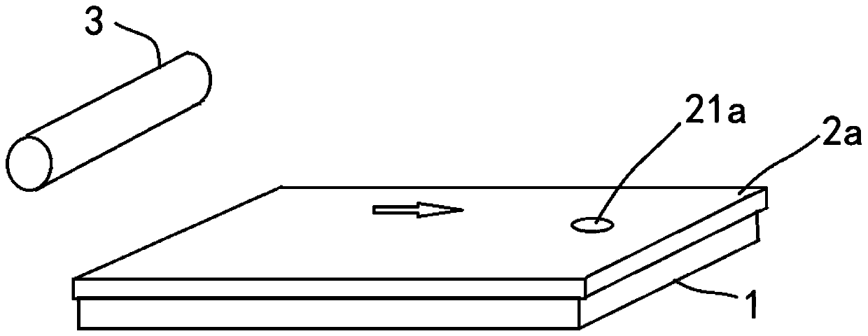
[0030] Such as image 3 As shown, the substrate alignment coating structure of the present invention includes a substrate 1 , an alignment plate 2 a and a printing mechanism 3 .
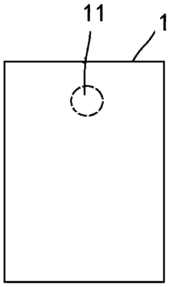
[0031] Such as figure 1 As shown, the substrate 1 includes at least one of an array substrate and a color filter substrate. The substrate 1 has a blind hole 11 through which the camera under the screen can transmit light. In this embodiment, a substrate 1 is taken as an example, such as an array substrate or a color filter substrate, to describe the alignment coating structure of the substrate of the present invention. The blind hole 11 on the array substrate or the color filter substrate is a circular hole, and its radius is set to R.
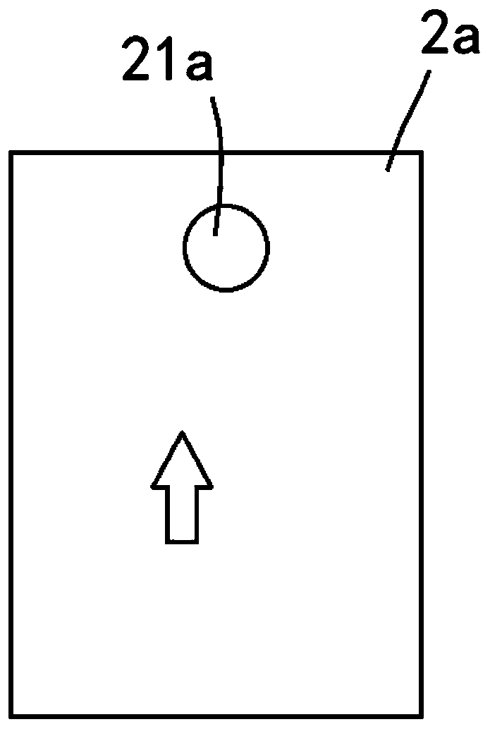
[0032] Such as figure 2 As shown, the alignment plate 2a has an opening 21a; before printing and coating polyimide liquid, the alignment plate 2a covers the substrate 1, and the opening 21a corresponds to the blind hole 11. In this embodiment, the opening 21a ...
Embodiment 2
[0041] Such as Figure 4As shown, the difference between embodiment 2 and embodiment 1 is that in embodiment 2, the problem of deformation of the alignment plate 2b during the printing process needs to be considered, so it needs to be considered during design, so in the printing direction, The radius of the opening 21b needs to deduct the amount of deformation of about 0-2000um, that is, when designing, the opening 21b is an elliptical hole, the direction of the short radius of the elliptical hole is parallel to the printing direction, and the direction of the short radius of the elliptical hole is The direction of the major radius is perpendicular to the printing direction. The long radius of the elliptical hole is R±5000um, and the short radius of the elliptical hole is 0-2000um smaller than the long radius of the elliptical hole.
[0042] In order to clearly explain the present invention, this embodiment also provides an alignment coating method for a substrate, which spec...
Embodiment 3
[0048] Such as Figure 5 As shown, the difference between embodiment 3 and embodiment 1 is that embodiment 3 provides a plurality of substrates 1 arranged in an array, and the alignment plate 2c has the same number of printing units 201 as the number of substrates 1 , each printing unit 201 has an opening 21 c , each printing unit 201 corresponds to a substrate 1 , and the opening 21 c on each printing unit 201 corresponds to the blind hole 11 on the substrate 1 . The design of the blind hole 11 may refer to the design of Embodiment 2 or the design of Embodiment 1, which will not be repeated here.
[0049] In order to clearly explain the present invention, this embodiment also provides an alignment coating method for a substrate, which specifically includes the following steps: For each component or device, see figure 1 , Figure 5 shown.
[0050] A plurality of substrates 1 and an alignment plate 2c are provided, each substrate 1 has a blind hole 11, and the alignment plat...
PUM
 Abstract
Description
Claims
Application Information
 - R&D
- Intellectual Property
- Life Sciences
- Materials
- Tech Scout
- Unparalleled Data Quality
- Higher Quality Content
- 60% Fewer Hallucinations
Browse by: Latest US Patents, China's latest patents, Technical Efficacy Thesaurus, Application Domain, Technology Topic, Popular Technical Reports.
© 2025 PatSnap. All rights reserved.Legal|Privacy policy|Modern Slavery Act Transparency Statement|Sitemap|About US| Contact US: help@patsnap.com