
Automatic forming shear pin device for electronic parts and components and process of automatic forming shear pin device

An electronic component and automatic molding technology, applied in the field of automation, can solve the problems of small plug-in machine market share and small effect gap

Pending Publication Date: 2019-08-02
SHENZHEN TUPURUI TECH CO LTD
View PDF0 Cites 3 Cited by
  • Summary
  • Abstract
  • Description
  • Claims
  • Application Information

AI Technical Summary

Problems solved by technology

[0002] The circuit and function control integration carrier of electronic products is a PCB board, and a variety of electronic components need to be inserted on the PCB board, such as capacitors, resistors, diodes, triodes, etc.; Arrange multiple manual stations on the board, and insert various components into the PCB board with the continuous flow of the PCB board; The plug-in efficiency has been improved, and the production cost has been reduced; however, the existing plug-in machine technology is not much different from the effect achieved by traditional manual plug-in. Small market share

Method used


Image

  • Automatic forming shear pin device for electronic parts and components and process of automatic forming shear pin device
  • Automatic forming shear pin device for electronic parts and components and process of automatic forming shear pin device
  • Automatic forming shear pin device for electronic parts and components and process of automatic forming shear pin device

Examples


Embodiment Construction

[0064] The present invention will be further described below in conjunction with accompanying drawing:

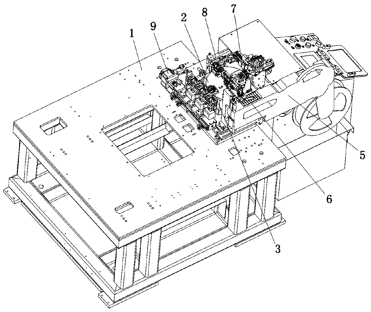
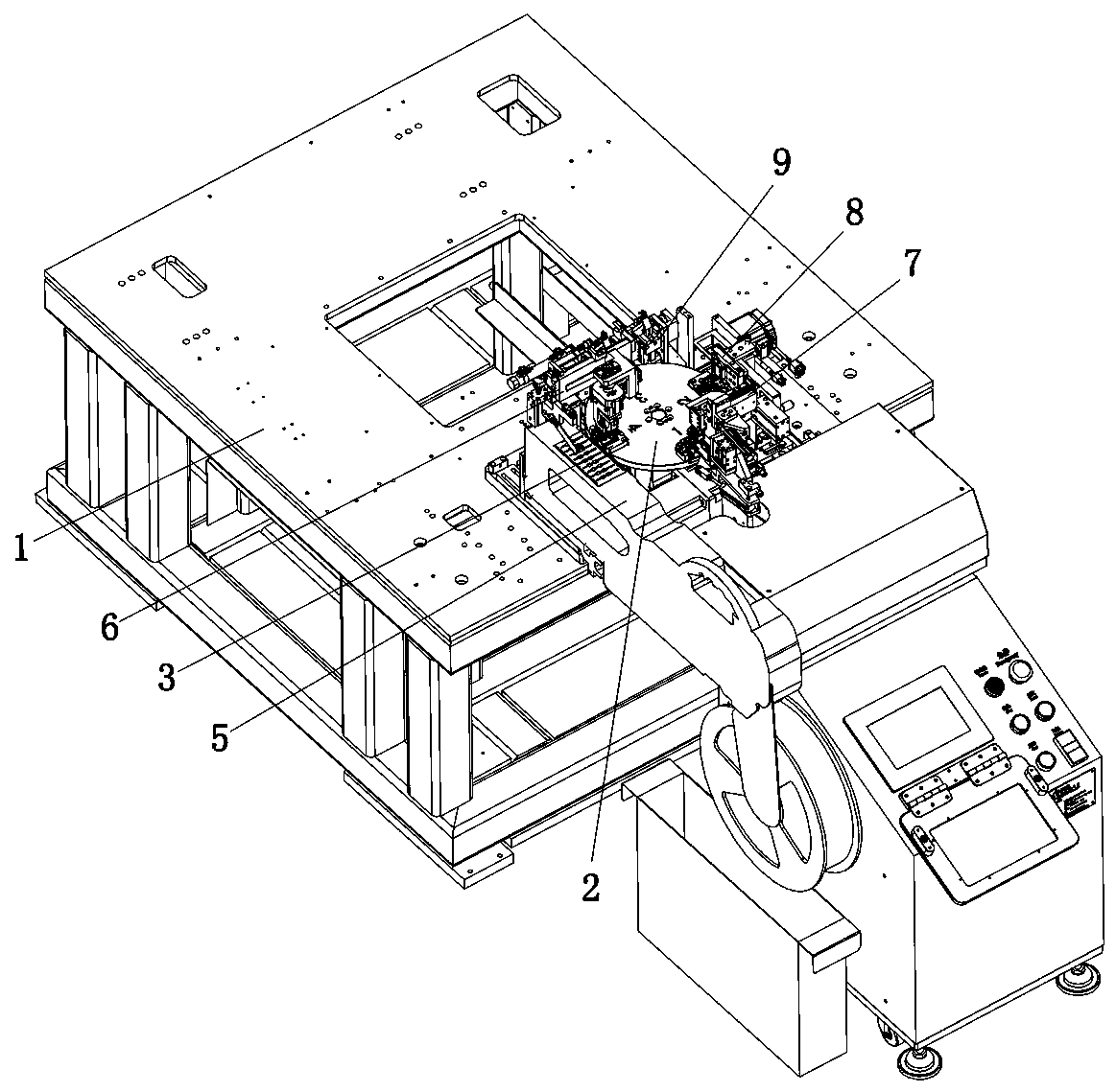
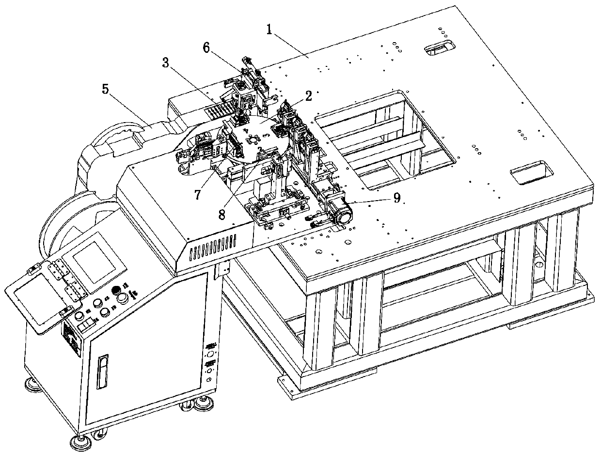
[0065] Such as Figure 1 to Figure 25 As shown, the technical scheme adopted by the present invention is as follows: an electronic component automatic forming and cutting foot device, including a turntable 2, a jig 3, an opening and closing mechanism 4, a feeding mechanism 5, a feeding mechanism 6, a forming mechanism 7, a cutting mechanism The foot mechanism 8 and the blanking mechanism 9, wherein the above-mentioned turntable 2 is rotatably arranged on the machine platform 1, and at least two processing stations are arranged at intervals along the circumferential direction on the turntable 2; the above-mentioned jig 3 includes at least two sets, The tool 3 is set at the processing station of the turntable 2, and rotates with the turntable 2; there is a storage space in the jig 3, and the component 0 to be processed is placed in the storage space. In the natural state, the c...


PUM


Abstract

The invention discloses an automatic forming shear pin device for electronic parts and components and a process of the automatic forming shear pin device. The automatic forming shear pin device comprises a rotary disc, at least two sets of jigs, an opening-closing mechanism, a supply mechanism, a loading mechanism, a forming mechanism, a shear pin mechanism and an unloading mechanism, wherein therotary disc is rotatably arranged on a machine table; the jigs are arranged on processing stations of the rotary disc; to-be-processed components and parts are placed in the jigs, and forming blocks are arranged at sides of the components and parts; the opening-closing mechanism is separately arranged below the jigs; the supply material is arranged on the machine table, and extends to one side ofthe rotary disc; the loading mechanism is arranged at one side of the supply mechanism; and the forming mechanism, the shear pin mechanism and the unloading mechanism are arranged on the machine table, and are sequentially arranged on the side part of the rotary disc in a spaced mode in a peripheral direction. The automatic forming shear pin device realizes transmission turning through an inclinedpushing block, utilizes a roller and a guide arc surface to realize linked opening-closing of a pin clamping assembly and an component and part clamping assembly, and effectively improves automationdegree of the forming shear pin for the components and parts, forming shear pin quality and efficiency.

Description

technical field [0001] The invention relates to the field of automation, in particular to an electronic component automatic molding and clipping device and its technology. Background technique [0002] The circuit and function control integration carrier of electronic products is a PCB board, and various electronic components need to be inserted on the PCB board, such as capacitors, resistors, diodes, triodes, etc.; Arrange multiple manual stations on the board, and insert various components into the PCB board with the continuous flow of the PCB board; The plug-in efficiency has been improved, and the production cost has been reduced; however, the existing plug-in machine technology is not much different from the effect achieved by traditional manual plug-in. The market share is not large. Before inserting, it is necessary to carry out various preprocessing on the incoming electronic components to meet the inserting requirements of different electronic components. [0003...

Claims


Application Information

Patent Timeline
IPC IPC(8): B21F11/00B21F1/00B21F23/00
CPCB21F11/00B21F1/004B21F23/00
Inventor 王建波钟勤
Owner SHENZHEN TUPURUI TECH CO LTD
Learn More