A method for improving the processing efficiency of titanium alloy cavity fillet

A processing efficiency, titanium alloy technology, applied in the direction of metal processing equipment, manufacturing tools, milling machine equipment, etc., can solve the problems of many types of tool specifications, inconsistent processing quality, serious tool gap, etc., to achieve consistent and stable processing quality and program capacity Small size, tool cost reduction effect

Active Publication Date: 2020-09-25
河南平原光电有限公司
View PDF7 Cites 0 Cited by
  • Summary
  • Abstract
  • Description
  • Claims
  • Application Information

AI Technical Summary

Problems solved by technology

[0004] Using thinning track, that is, radial layered milling, many types of tools are used, too many tool tracks, large program capacity, low processing efficiency, serious tool gap, and inconsistent processing quality

Method used


Image

  • A method for improving the processing efficiency of titanium alloy cavity fillet
  • A method for improving the processing efficiency of titanium alloy cavity fillet
  • A method for improving the processing efficiency of titanium alloy cavity fillet

Examples


Embodiment 1

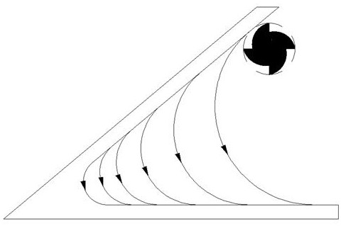
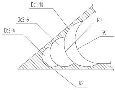
[0024] see image 3 , the processing method of the groove fillet R2:

[0025] Step 1. Milling the bottom of the cavity to form a fillet with a radius of 2, which is carried out in three steps,

[0026] The first step: the rough machining of the fillet of the cavity, the diameter Dc is selected 1 =10 rough machining milling cutter, keep the rough machining milling cutter to make feed motion along the axial direction, use the cutting edge at the bottom of the rough machining milling cutter to perform combined drilling and milling cutting on the bottom of the groove cavity, rough milling with large allowance, groove Rough machining of cavity fillet A R5 fillet is processed at the bottom of the cavity;

[0027] The second step: semi-finishing the fillet of the cavity, the diameter Dc is selected 2 =6 semi-finishing milling cutter, keep the semi-finishing milling cutter to do feed motion along the axial direction, utilize the cutting edge at the bottom of the semi-finishing cutt...

Embodiment 2

[0033] Processing method of groove fillet R4:

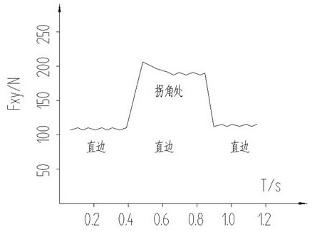
[0034] Step 1. Mill the bottom of the cavity to form a fillet with a radius of 4. Select a cutting milling cutter with a diameter of Dc=8. During milling, keep the cutting milling cutter moving in the axial direction, and use the bottom of the cutting milling cutter to The cutting edge performs drilling and milling combined cutting on the bottom of the groove cavity. When the cutting milling cutter is milling, the milling parameters are 2000 rpm, the cutting width is 1 / 3~1 / 2 of the diameter of the cutting milling cutter, and the feed rate is 0.08~0.25min / tooth, the cutting milling cutter is a titanium alloy cemented carbide milling cutter, and the cutting edge angle of the cutting milling cutter is 87° or 90°.

[0035] Step 2: Use layered milling to process the groove allowance outside the fillet. For the residue after milling in step 1, use an end mill to remove it to form a straight edge of the groove.

[0036] The processing ...


PUM


Abstract

The invention discloses a method for improving the machining efficiency of a groove cavity circular bead of a titanium alloy. The method comprises the steps that 1, the groove cavity bottom is milledto form a circular bead with the radius R, a cutting milling cutter is selected, the cutting milling cutter keeps doing feeding motion in the axial direction when milling is conducted, and drilling and milling combined cutting is conducted on the groove cavity bottom through a cutting edge arranged at the bottom of the cutting milling cutter; and 2, the groove cavity margin on the outer side of the circular bead is machined by adopting a layered milling mode to form a groove cavity straight edge. The method is suitable for machining the groove cavity circular bead of a difficult-to-machine material such as the titanium alloy and parts with more groove cavity circular beads; and compared with a traditional radial layered milling machining mode, the machining efficiency is improved by 30% orabove, and the cutter cost is reduced by 25% or above.

Description

technical field [0001] The invention relates to the technical field of titanium alloy groove cavity processing, in particular to a method for improving the processing efficiency of titanium alloy groove cavity round corners. Background technique [0002] With the continuous improvement of the performance requirements of modern warfare on weapons and equipment and the development of light weight, the integrated design of product structural parts has become the development trend of modern weapons and equipment, that is, to integrate multiple functional structural parts into one structural part to reduce assembly. The accumulation of errors reduces the difficulty of single-piece processing, while reducing product weight, improving assembly efficiency, improving product reliability, and shortening the product development cycle. The integrated structure of titanium alloy is the most ideal and has become the development direction of the promotion and application of photoelectric m...

Claims


Application Information

Patent Timeline
Patent Type & Authority Patents(China)
IPC IPC(8): B23C3/12
CPCB23C3/12
Inventor 王三民廉继西张涛刘菊花梁兵孙俊霞李红星王明华赵淑君叶培娟
Owner 河南平原光电有限公司
Why Eureka
Try Eureka