LNG large water bath type gasification system and method utilizing same

A gasification system, water bath technology, applied in the direction of container filling method, container discharge method, heat exchanger type, etc., can solve the problems of inability to realize LNG gasification heating of large LNG storage tanks, limit the temperature range of heating, etc. Achieve the effect of avoiding high equipment investment, large heat transfer coefficient, and efficient LNG gasification heating

Inactive Publication Date: 2019-08-02
HEPU ENERGY ENVIRONMENTAL TECHNOLOGY CO LTD
View PDF0 Cites 0 Cited by
  • Summary
  • Abstract
  • Description
  • Claims
  • Application Information

AI Technical Summary

Problems solved by technology

[0004] Another LNG gasification heating method is a water bath heater, but the water temperature cannot be lower than zero, so the temperature range of its heating is limited, so a single water bath heater cannot realize the LNG gasification heating function of a large LNG storage tank

Method used


Image

  • LNG large water bath type gasification system and method utilizing same

Examples


Embodiment 1

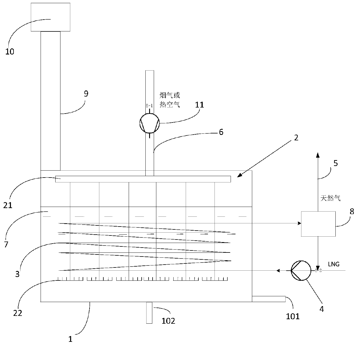
[0042] This embodiment provides an LNG large-scale water bath gasification system, such as figure 1 As shown, it includes a liquid heating water bath 1, a heat source gas injection and distribution device 2, a LNG vaporization heating heat exchange tube bundle 3, a booster pump 4, a natural gas pipeline 5, and a heat source gas connecting pipeline 6; the liquid heating water bath 1 The heat exchange liquid medium 7 is contained inside; the gas inlet of the heat source gas injection and distribution device 2 is connected to the heat source gas connecting pipeline 6, and the gas outlet is located in the liquid heating water bath 1; the LNG gas The chemical heating and heat exchange tube bundle 3 is arranged in the liquid heating water bath 1, one end of which is connected to the booster pump 4, and the other end is connected to the natural gas pipeline 5; the booster pump 4 is connected to an LNG storage device.

[0043] In this embodiment, the system further includes a gas-liquid...

Embodiment 2

[0063] This embodiment provides a design method of the system as described in Embodiment 1, including the following steps:

[0064] S1. According to the capacity of the LNG storage device, the flow rate of the booster pump, and the required gas supply temperature of the final natural gas, the heat exchange required for gasification of the set flow rate of LNG is calculated according to the following formula:

[0065] Q LNG total = F LNG *Q gasification +F LNG *(T for -T LNG )*C p gas

[0066] Q LNG total The total energy required to vaporize LNG and reach the supply temperature, kJ / h; Q gasification Energy required for LNG gasification, kJ / h; F LNG Is the LNG flow rate, kg / h; C p gas Is the specific heat capacity of natural gas, kJ / kg℃; T for Is the temperature of external natural gas supply, ℃; T LNG Is the temperature after LNG gasification, ℃;

[0067] S2 According to the type of heat exchange tube selected, query the heat exchanger design manual to obtain the air convect...


PUM


Abstract

The invention discloses an LNG large water bath type gasification system and a method utilizing the same. The system comprises a liquid heating water bath, a heat source gas injection and distributiondevice, an LNG gasification heating and heat exchange tube bundle, a booster pump, a natural gas pipeline and a heat source gas connecting pipeline, wherein a heat exchange liquid medium is containedin the liquid heating water bath, a gas inlet of the heat source gas injection and distribution device communicates with the heat source gas connecting pipeline, and a gas outlet of the heat source gas injection and distribution device is located in the liquid heating water bath; and the LNG gasification heating and heat exchange tube bundle is arranged in the liquid heating water bath, one end of the LNG gasification heating and heat exchange tube bundle communicates with the booster pump, the other end of the LNG gasification heating and heat exchange tube bundle communicates with the natural gas pipeline, and the booster pump communicates with an LNG storage device. The cost required by LNG gasification can be effectively reduced by utilizing the system.

Description

Technical field [0001] The invention relates to LNG gasification heating technology, in particular to a system and method for heating and gasifying LNG by using a low-temperature resistant organic aqueous solution as a water bath heat source. Background technique [0002] According to my country's mid- and long-term energy development plan, natural gas will become a highlight of my country's energy development strategy and one of the pillars of green energy. In the future, my country will import a large amount of natural gas, most of which will be transported to China in the form of liquefied natural gas (LNG). A large amount of imported LNG also carries a large amount of cold energy. At present, the gasification of LNG mainly relies on seawater heat exchange to heat and gasify. [0003] The biggest problem with seawater heat exchangers and seawater pipelines is the need for special metal materials. The manufacturing costs of pipes and heat exchanger plates are high. Generally, ti...

Claims


Application Information

Patent Timeline
Patent Type & Authority Applications(China)
IPC IPC(8): F17C7/04F17C13/00F24H7/00F28D1/047
CPCF17C7/04F17C13/00F17C2221/033F17C2227/0142F17C2227/0309F24H7/00F28D1/047
Inventor 崔华杨豫森陈辉
Owner HEPU ENERGY ENVIRONMENTAL TECHNOLOGY CO LTD
Why Eureka
Try Eureka