Design method for condensing pipe interval of loop heat pipe

A design method and loop heat pipe technology, applied in the field of heat pipes, can solve problems affecting fluid heat transfer, narrow space A area, increased flow resistance, etc., to achieve uniform fluid division, improve the effect of steady flow, and promote the effect of smooth flow

Inactive Publication Date: 2019-08-02
SHANDONG UNIV
View PDF6 Cites 0 Cited by
  • Summary
  • Abstract
  • Description
  • Claims
  • Application Information

AI Technical Summary

Problems solved by technology

The impact phenomenon will cause large noise vibration and mechanical shock, causing damage to the equipment
[0006] In addition, due to the existence of vapor-liquid problems, the vapor and liquid are separated from each other in the heat exchange, so that the gas and liquid cannot be fully mixed, which affects the heat exchange effect, resulting in uneven heat exchange, and local temperatures are too high or too low
[0007] The inventor has also designed a variety of heat pipe devices to solve the above problems in the previous application, such as multi-pipe type, but this kind of device has been found in operation, because the pipes are closely combined, so the heat pipe formed between the three pipes Space A is relatively small, because space A is formed by the convex arc of three pipes, so most of space A is narrow, which will make it difficult for the fluid to enter and pass through, resulting in a short circuit of the fluid, which affects the heat exchange of the fluid and cannot play a good role. steady flow
Simultaneously because the many tubes of above-mentioned structure are combined together, manufacture difficulty
Another example is the 2017102671998 structure. Although this structure solves the fluid short circuit phenomenon, there is a problem that the flow area is greatly reduced, resulting in an increase in flow resistance.
Another example is the annular partition device of 2017102949490. In the annular structure, the partition device adopts a ring structure, which leads to the uneven separation of the annulus of the partition device in the circumferential direction, and because of the ring structure, the positions of the four included angles of the annulus appear less than Acute angles of 90 degrees, which can cause problems with shorting fluid flow at acute angles less than 90 degrees
[0008] In view of the above problems, the present invention improves on the basis of the previous invention, and provides a new heat pipe, so as to solve the problem of uneven heat transfer in the case of heat pipe heat exchange.

Method used


Image

  • Design method for condensing pipe interval of loop heat pipe
  • Design method for condensing pipe interval of loop heat pipe
  • Design method for condensing pipe interval of loop heat pipe

Examples


Embodiment Construction

[0070] The specific embodiments of the present invention will be described in detail below in conjunction with the accompanying drawings.

[0071] In this article, if there is no special explanation, when it comes to formulas, " / " means division, and "×" and "*" mean multiplication.

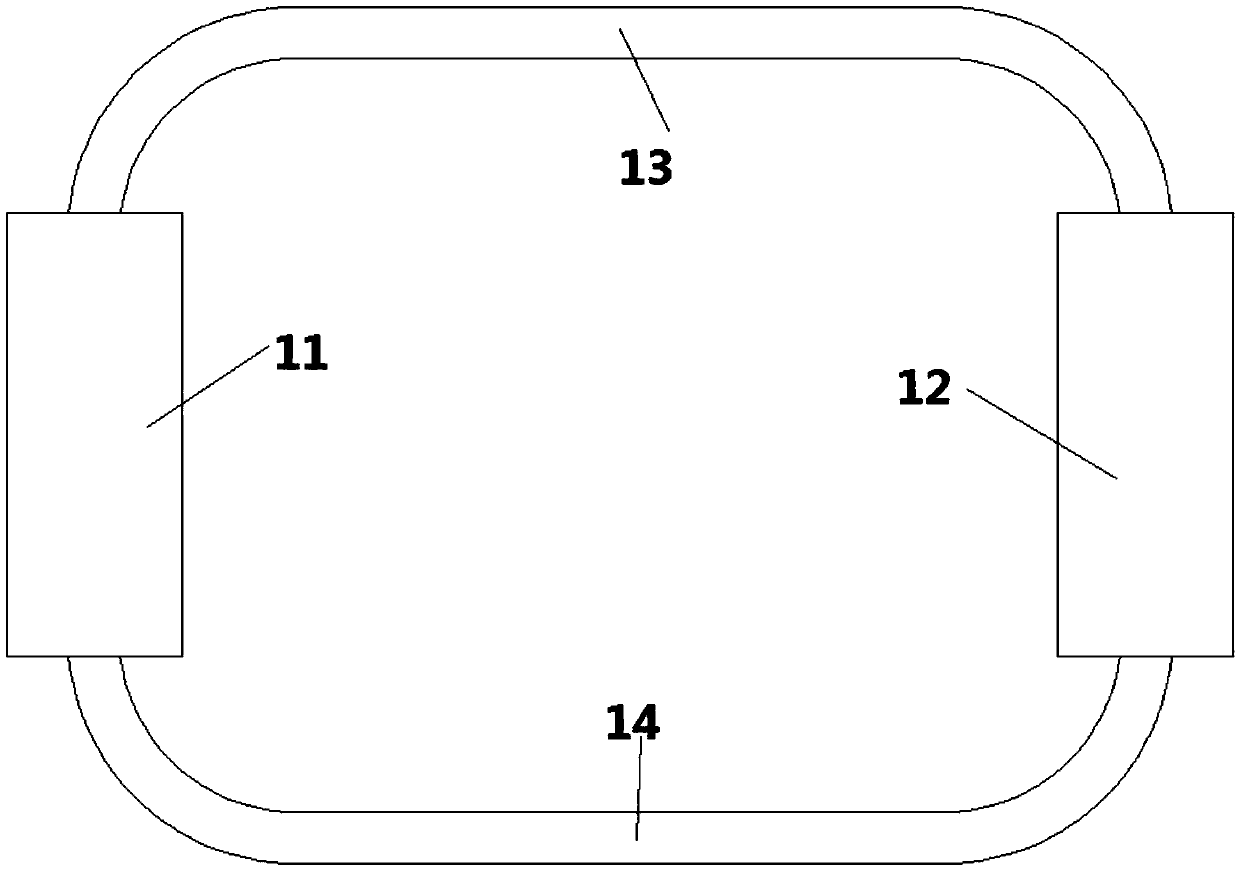
[0072] Such as figure 1 A loop heat pipe 1 shown includes an evaporating part 11, a condensing part 12, an adiabatic part 13 connecting the evaporating part and a condensing part, and a return part 14. The fluid absorbs heat and evaporates in the evaporating part 11, and enters the condensing part through the adiabatic part 13 12. Condensate after heat exchange in the condensing part 12, and the condensed fluid returns to the evaporating part 11 through the return pipe 14. Preferably, the return section is also insulated.

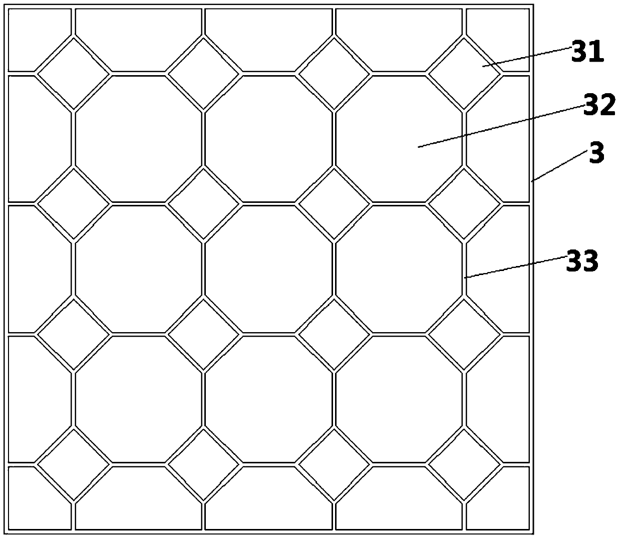
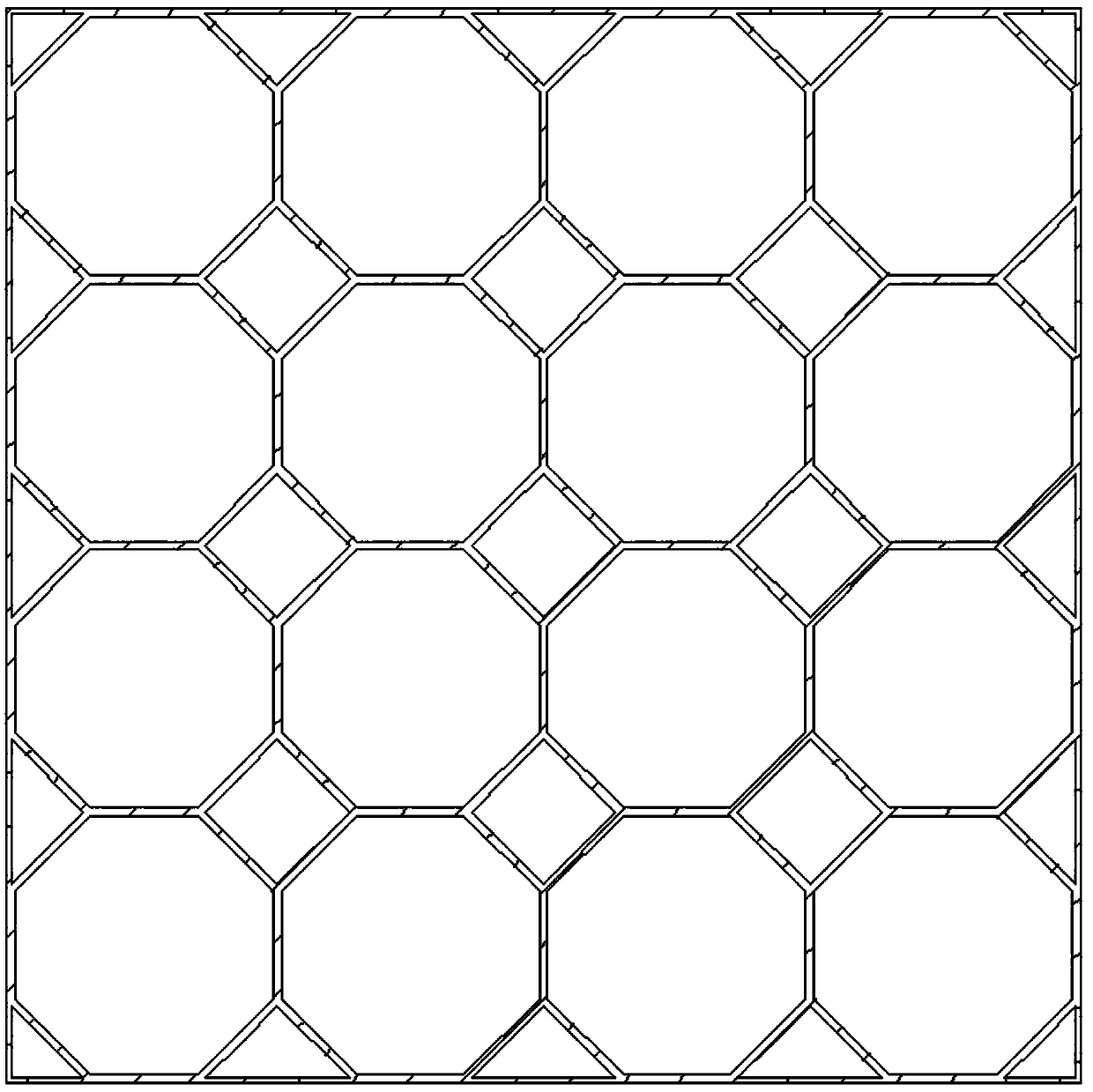
[0073] As an improvement, the evaporating part includes a heat absorption pipe, and a partition device 3 is arranged inside the heat absorption pipe, and the structure of th...


PUM


Abstract

A design method of a loop heat pipe comprises an evaporating portion, a condensing portion, a heat insulating portion and a backflow portion, wherein the heat insulating portion and the backflow portion are connected with the evaporating portion and the condensing portion; fluid absorbs heat and evaporates in the evaporating potion, and enters the condensing portion through the heat insulating portion; after exchanging heat in the condensing portion, the fluid is condensed; the condensed fluid returns to an evaporating header through a backflow pipe; the condensing portion comprises a plurality of condensing pipes which are of a parallel structure in parallel connection; the distance between adjacent separating devices is S1, and the side length of a square is L1; each condensing pipe is asquare cross section; the side length of each condensing pipe is L2; and the interval between the centers of adjacent cooling pipes is S2. The design method for the condensing pipe interval of the loop heat pipe is put forwards, heat transfer is strengthened, meanwhile vibration of heat absorbing pipes is weakened, and the noise level is lowered.

Description

technical field [0001] The invention belongs to the field of heat pipes, in particular to a loop heat pipe. Background technique [0002] Heat pipe technology is a heat transfer element called "heat pipe" invented by George Grover of Los Alamos National Laboratory in the United States in 1963. It makes full use of the principle of heat conduction and phase change medium. The rapid heat transfer properties of the heat pipe quickly transfer the heat of the heating object to the heat source, and its thermal conductivity exceeds that of any known metal. [0003] Heat pipe technology was widely used in aerospace, military and other industries before. Since it was introduced into the radiator manufacturing industry, people have changed the traditional radiator design ideas and got rid of the single heat dissipation mode that only relies on high air volume motors to obtain better heat dissipation. The use of heat pipe technology enables the radiator to obtain a satisfactory heat e...

Claims


Application Information

Patent Timeline
IPC IPC(8): F28D15/02
CPCF28D15/0266
Inventor 郭春生李言伟陈子昂江程年显勃马军谷潇潇薛于凡李红云武晓阳辛华钰
Owner SHANDONG UNIV
Why Eureka
Try Eureka