Micro-nano metal structure for realizing circular dichroism and application thereof

A metal structure and circular dichroism technology, applied in the field of micro-nano photonics, can solve the problems of difficult adjustment of circular dichroism, complex structure of planar chiral structure, etc., and achieve clear physical mechanism, simple structure and good application foreground effect

Inactive Publication Date: 2019-08-02
SHAANXI NORMAL UNIV
View PDF5 Cites 9 Cited by
  • Summary
  • Abstract
  • Description
  • Claims
  • Application Information

AI Technical Summary

Problems solved by technology

[0005] In order to solve the problem that the structure of the planar chiral structure is complex and its circular dichroism is difficult to adjust in the prior art, the present invention provides a micro-nano metal structure for realizing circular dichroism and its use method, which is easy to use The gap between...

Method used


Image

  • Micro-nano metal structure for realizing circular dichroism and application thereof
  • Micro-nano metal structure for realizing circular dichroism and application thereof
  • Micro-nano metal structure for realizing circular dichroism and application thereof

Examples


Embodiment 1

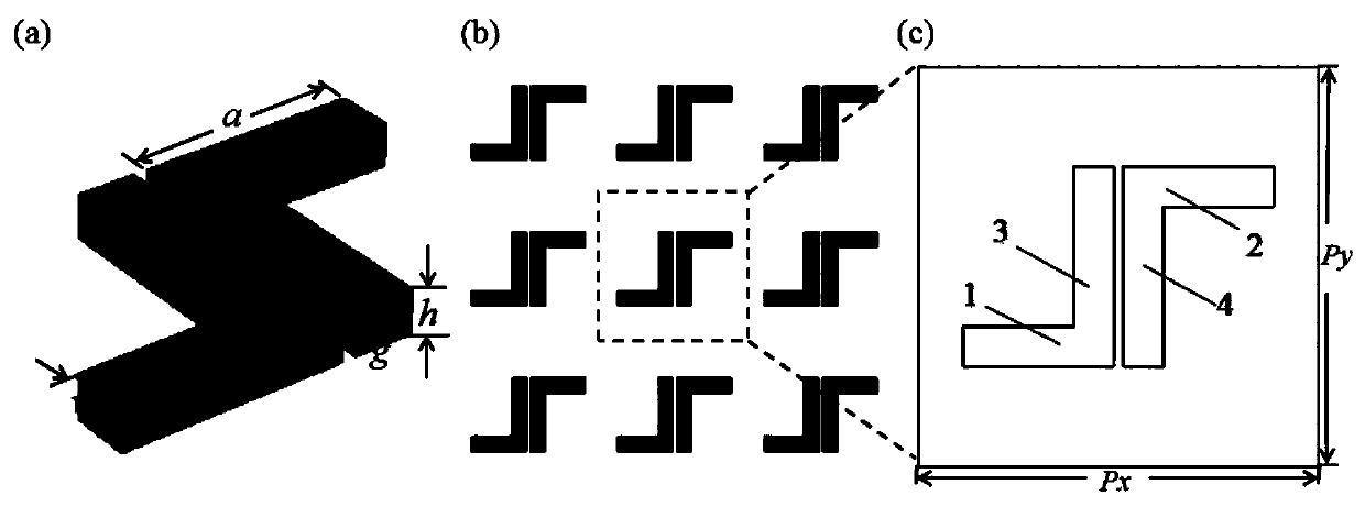
[0027] A micro-nano metal structure that realizes circular dichroism. The micro-nano metal structure is formed by plane connection of multiple periodic units with the same structure. Each periodic unit contains a double L-shaped structural unit. Each structural unit includes a horizontal Body I1, horizontal body II2, vertical body I3, vertical body II4, horizontal body I1 is vertically connected to vertical body I3, horizontal body II2 is vertically connected to vertical body II4; horizontal body I1 and horizontal body II2 are set in parallel, vertical body I3 is connected to vertical body Body II4 is arranged in parallel, horizontal body I1, horizontal body II2, vertical body I3, and vertical body II4 are all made of precious metal material Au.

[0028] in particular:

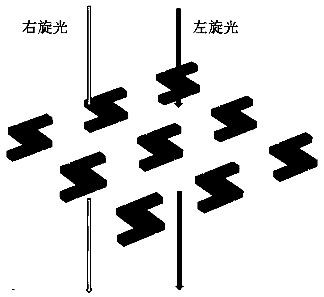
[0029] The micro-nano metal structure of this embodiment belongs to the planar chiral structure. When the incident light irradiates the micro-nano metal structure of this embodiment, it produces different abso...

Embodiment 2

[0040]Based on the micro-nano metal structure for realizing circular dichroism disclosed in Example 1, this embodiment discloses the application of a micro-nano metal structure for realizing circular dichroism, which specifically includes the following steps:

[0041] Step 1. Adjust the distance g between vertical body I3 and vertical body II4, measure and record different distances g and their corresponding CD signals, so that the distance g between vertical body I3 and vertical body II4 corresponds to the CD signal one by one, Get the corresponding table as Image 6 shown;

[0042] Step 2, at the first temperature T 1 Next, fill the thermal expansion material between the vertical body I3 and the vertical body II4, turn on the light source and detector, measure and record the CD signal of the micro-nano metal structure at this temperature, and determine the corresponding table through the corresponding table obtained in step 1. The distance g between vertical body Ⅰ3 and ve...


PUM

PropertyMeasurementUnit
Lengthaaaaaaaaaa
Lengthaaaaaaaaaa

Abstract

The invention relates to the technical field of micro-nano opticals and specifically relates to a micro-nano metal structure for realizing circular dichroism and application thereof. The circular dichroism of the micro-nano metal structure provided by the invention is dynamically adjusted through adjustment of a space g between a vertical body I and a vertical body II and coupling degree between two L-shaped structures of the micro-nano metal structure is changed through utilization of a size of the space g between the vertical body I and the vertical body II, so the circular dichroism is dynamically adjusted. Conventional circular dichroism adjustment is mainly realized in a coupling mode in a height direction, so structure preparation is complex and a requirement for an experiment condition and a detection instrument is very high. According to the micro-nano metal structure for realizing the circular dichroism provided by the invention, operation for adjusting a circular dichroism signal is simple and convenient and is easy to realize. A new thought for dynamic adjustment of a planar circular dichroism signal is provided.

Description

technical field [0001] The invention belongs to the technical field of micro-nano photonics, and in particular relates to a micro-nano metal structure for realizing circular dichroism and its application. Background technique [0002] Chirality refers to the property that itself cannot completely coincide with the mirror image, and a chiral substance and its mirror image are called chiral counterparts. The structure of many substances in nature has chirality, such as protein, DNA and so on. Chirality is particularly important to the significance of life, so detecting the chirality of substances has become a research hotspot for many researchers. Circular dichroism (CD) is usually used to detect the chirality of substances or structures. CD can be defined as the difference in the absorption rate of chiral media for different circularly polarized light, and the difference is circular dichroism. [0003] Since chiral signals such as biomolecules are relatively weak and usuall...

Claims


Application Information

Patent Timeline
IPC IPC(8): G01N25/16G02B27/28
CPCG01N25/16G02B27/286
Inventor 景志敏张中月
Owner SHAANXI NORMAL UNIV
Why Eureka
Try Eureka