
High-voltage separation transformer

A high-voltage separation and transformer technology, applied in the field of transformers, can solve the problems of increasing the number of microwave high-voltage transformer components, reducing the withstand voltage and life of microwave high-voltage transformers, reducing the safety of microwave equipment, etc. The effect of life and circuit simplicity

Pending Publication Date: 2019-08-02
山东骏风电子有限公司
View PDF0 Cites 0 Cited by
  • Summary
  • Abstract
  • Description
  • Claims
  • Application Information

AI Technical Summary

Problems solved by technology

[0003] The problems and shortcomings of the microwave high-voltage transformer are: because the withstand voltage between each turn of the high-voltage coil of the microwave high-voltage transformer is certain, the designed voltage of the microwave high-voltage transformer is too high, and the voltage between each turn will also be high, which will cause the coil Intermittent breakdown, burning the microwave high-voltage transformer, so that the voltage of the microwave high-voltage transformer can only reach around 2000V. If the voltage is further increased, the withstand voltage and life of the microwave high-voltage transformer will be greatly reduced. Realize high-voltage double voltage, thereby increasing the number of components of microwave high-voltage transformers, and reducing the overall safety of microwave equipment

Method used


Image

  • High-voltage separation transformer
  • High-voltage separation transformer
  • High-voltage separation transformer

Examples


Embodiment Construction

[0019] The implementation of the present invention will be illustrated by specific specific examples below, and those skilled in the art can easily understand other advantages and effects of the present invention from the contents disclosed in this specification.

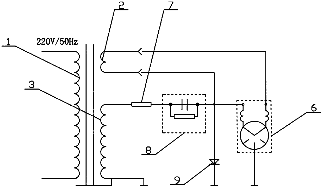
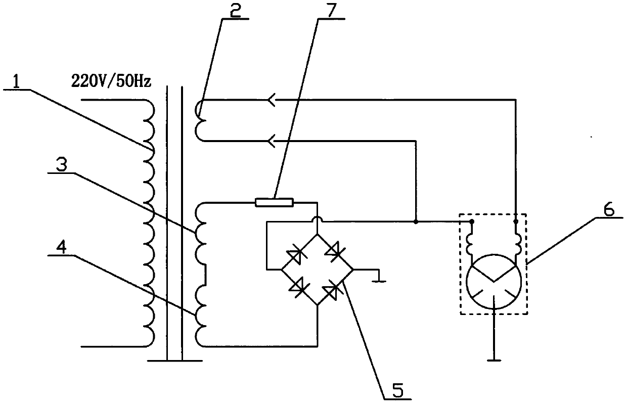
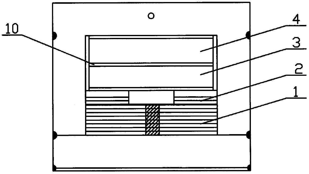
[0020] according to figure 2 , image 3 As shown: this embodiment provides a high-voltage separation transformer, including a magnetron 6, a transformer body and its primary coil 1 and secondary coil, and the coupling connection between the primary coil 1 and the secondary coil, wherein:

[0021] The secondary coil includes a secondary B1 coil 2 and two first secondary B2 coils 3 and second secondary B2 coils 4 arranged in series, the primary coil 1 is located at the bottom of the transformer body, the first secondary B2 coil 3, the second secondary coil 4 The secondary B2 coils 4 are respectively located on the upper part of the transformer body, and the secondary B1 coil 2 is arranged between the primary coil 1,...


PUM


Abstract

The invention relates to a high-voltage separation transformer, which comprises a magnetron, a transformer body and a primary coil and secondary coil thereof, wherein the primary coil and the secondary coil are in coupling connection, the secondary coil includes a secondary B1 coil and at least two secondary B2 coils arranged in a series connection manner; two ends of the secondary B1 coil are electrically connected with the magnetron; and the secondary B2 coils are electrically connected with the magnetron through a high-voltage rectifier bridge circuit, and a fuse tube is connected in seriesin the circuit between the secondary B2 coils. The high-voltage separation transformer is reasonable in design, the voltage is graded through adopting two or more secondary B2 coils, the voltage between the turns of the coils is lowered, the voltage between the layers of the coils remains unchanged, and the withstand voltage safety of the high-voltage transformer is ensured. Meanwhile, the service life of the transformer is prolonged, and the high-voltage capacitor and high-voltage diode voltage doubling circuit part is reduced, thereby enabling the circuit to be more concise, and enabling the system to be more stable.

Description

technical field [0001] The invention relates to the technical field of transformers, in particular to a high-voltage separation transformer. Background technique [0002] The function of the microwave high-voltage transformer in the prior art is to transform the mains power into a high voltage between 2000 volts and 2400 volts, and then increase the voltage to 4000 volts through high-voltage capacitors and high-voltage diodes, and then supply it to the magnetron. Meet the working voltage of the magnetron. [0003] The problems and shortcomings of the microwave high-voltage transformer are: because the withstand voltage between each turn of the high-voltage coil of the microwave high-voltage transformer is certain, the designed voltage of the microwave high-voltage transformer is too high, and the voltage between each turn will also be high, which will cause the coil Intermittent breakdown, burning the microwave high-voltage transformer, so that the voltage of the microwave ...

Claims


Application Information

Patent Timeline
Patent Type & Authority Applications(China)
IPC IPC(8): H01F27/28H01F27/40H01F38/00
CPCH01F27/28H01F27/40H01F27/402H01F38/00H01F2038/003
Inventor 弭保森祝红梅
Owner 山东骏风电子有限公司
Learn More