Antenna matching device

An antenna matching and antenna technology, applied in the direction of antenna support/installation device, antenna, antenna parts, etc., can solve the problems of antenna and RF front-end mismatch, port standing wave difference, shorten tuning time, etc., to shorten the tuning time , Measuring the tuning impedance and satisfying the effect of frequency hopping

Inactive Publication Date: 2019-08-02
HEBI TIANHAI ELECTRONICS INFORMATION SYST
View PDF8 Cites 3 Cited by
  • Summary
  • Abstract
  • Description
  • Claims
  • Application Information

AI Technical Summary

Problems solved by technology

[0007] The technical problem mainly solved by the present invention is to provide an antenna matching device to solve the problems of mismatch between the antenna and the radio frequency front end and the difference of port standing waves, and at the same time achieve the purpose of accurately measuring the tuning impedance, shortening the tuning time and meeting the needs of frequency hopping

Method used


Image

  • Antenna matching device
  • Antenna matching device
  • Antenna matching device

Examples


Embodiment Construction

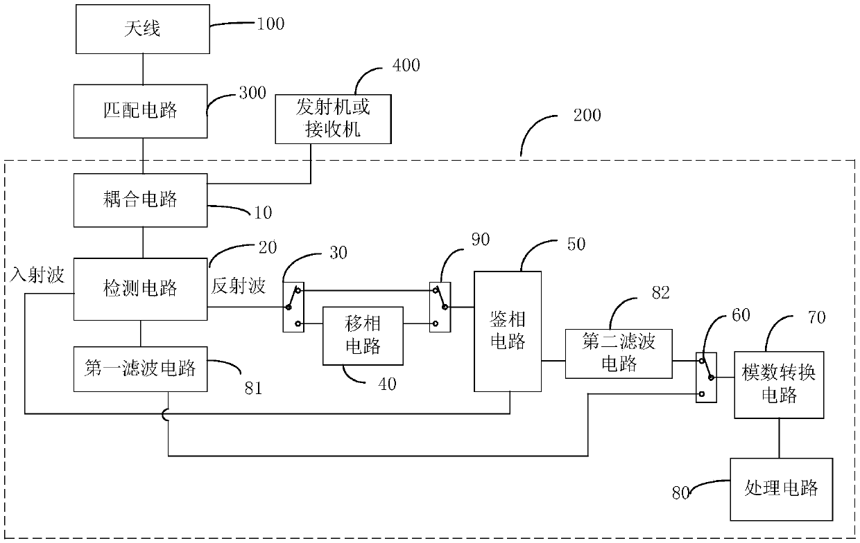
[0019] Please refer to figure 1 , is a schematic structural diagram of the antenna matching device of the present invention. The antenna matching device includes a measurement circuit 200, connected to the antenna 100, used to obtain the modulus and phase of the complex reflection coefficient of the antenna 100 and obtain the antenna 100 after calculating the modulus and phase of the complex reflection coefficient and output the complex impedance; and

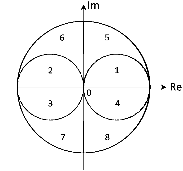
[0020] The matching circuit 300 is connected between the measuring circuit 200 and the antenna 100, and stores the correspondence between complex impedance and area, the matching circuit 300 receives the complex impedance output by the measuring circuit 200 and according to the stored complex impedance The corresponding relationship with the area finds the area corresponding to the received complex impedance, and adjusts the parameters of the area so that the antenna 100 matches the transmitter or the receiver.

[0021] Where...


PUM


Abstract

The invention discloses an antenna matching device. The antenna matching device comprises a measuring circuit which is connected with an antenna and used for obtaining the mode and the phase of the complex reflection coefficient of the antenna, calculating the mode and the phase of the complex reflection coefficient to obtain the complex impedance of the antenna and outputting the complex impedance; a matching circuit which is connected between the measuring circuit and the antenna and stores a corresponding relation between complex impedance and an area, wherein the matching circuit receivesthe complex impedance output by the measuring circuit and finds out an area corresponding to the received complex impedance according to the stored corresponding relation between the complex impedanceand the area and adjusts the parameters of the area to enable the antenna to be matched with a transmitter or a receiver, so as to solve the problems of mismatch between the antenna and the radio frequency front end and port standing wave difference, and achieve the purposes of accurately measuring the tuning impedance, shortening the tuning time and meeting the frequency hopping requirement.

Description

technical field [0001] The invention relates to the field of antenna tuning, in particular to an antenna matching device. Background technique [0002] The antenna is one of the most critical components of radio communication equipment, and the standing wave of the antenna limits the frequency bandwidth. It is usually required that the standing wave ratio of the antenna should be controlled within 2.0, but the standing wave of the antenna whose frequency band spans several times can only be within 3.0 or even 4.0, which causes a serious mismatch between the power amplifier and the antenna, and the output efficiency of the power amplifier is reduced. There is also a serious mismatch between the front end of the machine and the antenna, which increases the noise figure and reduces the receiving sensitivity. For wide-band antennas, the frequency band spans multiple frequency ranges, and it is difficult to balance the standing wave and gain in the entire frequency range. In ord...

Claims


Application Information

Patent Timeline
Patent Type & Authority Applications(China)
IPC IPC(8): H04B1/04H04B1/18H01Q1/24H03H7/40
CPCH01Q1/243H03H7/40H04B1/0458H04B1/18
Inventor 冯志成翁美丽
Owner HEBI TIANHAI ELECTRONICS INFORMATION SYST
Why Eureka
Try Eureka