Channel estimation method and device
A technology for channel estimation and indication information, which is applied in the field of precoding and can solve problems such as large indication overhead.
- Summary
- Abstract
- Description
- Claims
- Application Information
AI Technical Summary
Problems solved by technology
Method used
Image
Examples
Embodiment 1
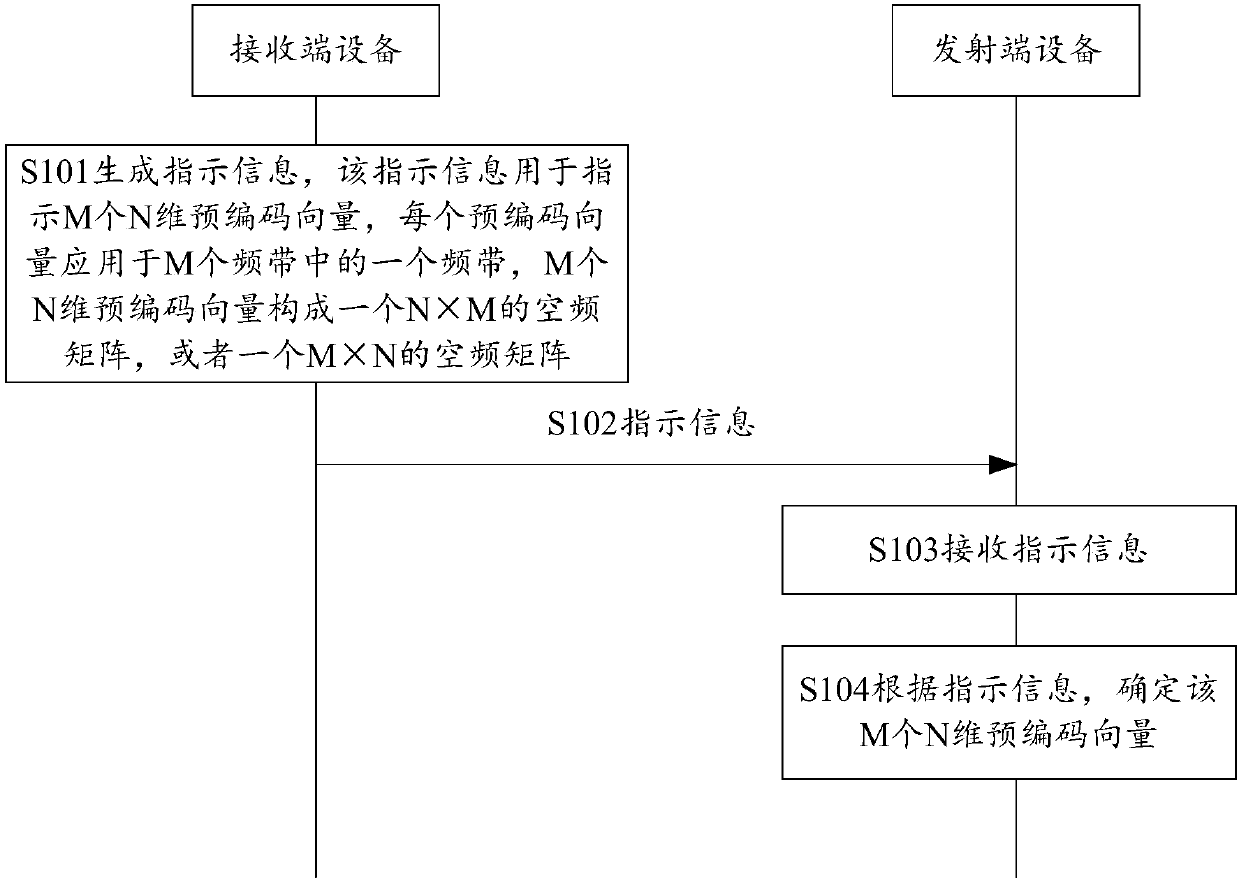
[0187] In this embodiment, M N-dimensional precoding vectors form an N×M space-frequency matrix H. Each N-dimensional precoding vector is used as a column vector of the space-frequency matrix H. The space-frequency matrix H is generated by weighted combination of multiple space-frequency component matrices. Each space-frequency component matrix is the product of a space-domain component vector and a conjugate transpose vector of a frequency-domain component vector.
[0188] Based on this, in this embodiment, the space-frequency matrix H can be expressed as the following formula:
[0189]
[0190] Wherein, W is the number of space-frequency component matrices. u 1w is the spatial domain component vector corresponding to the wth spatial frequency component matrix. u 2w is the frequency-domain component vector corresponding to the wth space-frequency component matrix, is u 2w The conjugate transpose vector of . is the wth space-frequency component matrix the weig...
Embodiment 2
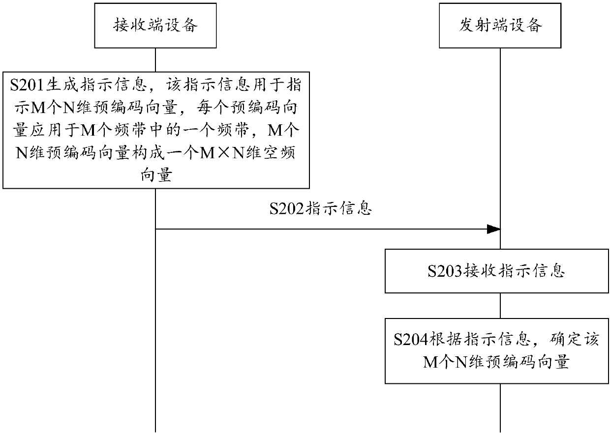
[0192] In this embodiment, M N-dimensional precoding vectors form an M×N space-frequency matrix H. The conjugate transpose vector of each N-dimensional precoding vector is used as a row vector of the space-frequency matrix H. The space-frequency matrix H is generated by weighted combination of multiple space-frequency component matrices. Each space-frequency component matrix is the product of a frequency-domain component vector and a conjugate transpose vector of the space-domain component vector.
[0193] Based on this, in this embodiment, the space-frequency matrix H can be expressed as the following formula:
[0194]
[0195] in, is u 1w The conjugate transpose vector of . The explanation of other parameters can refer to the above, and will not be repeated here.
[0196] Based on any one of the first and second embodiments above, the spatial domain component vectors corresponding to different spatial frequency component matrices may be the same or different. The...
Embodiment 3
[0269] In this embodiment, M N-dimensional precoding vectors form an N×M space-frequency matrix H. Each N-dimensional precoding vector is used as a column vector of the space-frequency matrix H. The space-frequency matrix H is generated by weighted combination of multiple space-frequency component matrices. Each space-frequency component matrix is selected from a set of space-frequency component matrices, or is generated by weighted combination of multiple sets of space-frequency basis matrices selected from space-frequency basis matrices. In this embodiment, the space-frequency base matrix is an N×M matrix. Each space-frequency basis vector or each space-frequency component matrix in the set of space-frequency component matrices may be a product of a space-domain basis vector and a conjugate transpose vector of a frequency-domain basis vector.
PUM
 Abstract
Description
Claims
Application Information
 - R&D
- Intellectual Property
- Life Sciences
- Materials
- Tech Scout
- Unparalleled Data Quality
- Higher Quality Content
- 60% Fewer Hallucinations
Browse by: Latest US Patents, China's latest patents, Technical Efficacy Thesaurus, Application Domain, Technology Topic, Popular Technical Reports.
© 2025 PatSnap. All rights reserved.Legal|Privacy policy|Modern Slavery Act Transparency Statement|Sitemap|About US| Contact US: help@patsnap.com


