Oil injector

A technology of oil injector and oil filling plug, which is applied in the direction of machines/engines, liquid displacement machinery, variable displacement pump components, etc., to achieve the effects of adjustable oil injection, compact structure and reliable use

Inactive Publication Date: 2019-08-06
HEFEI GENERAL MACHINERY RES INST
View PDF4 Cites 0 Cited by
  • Summary
  • Abstract
  • Description
  • Claims
  • Application Information

AI Technical Summary

Problems solved by technology

[0003] In order to solve the technical problems of normal lubricating fluid supply when providing high pressure and dealing with harsh working environment existing in the prior art, the present invention provides a lubricator

Method used


Image

  • Oil injector
  • Oil injector
  • Oil injector

Examples


Embodiment 1

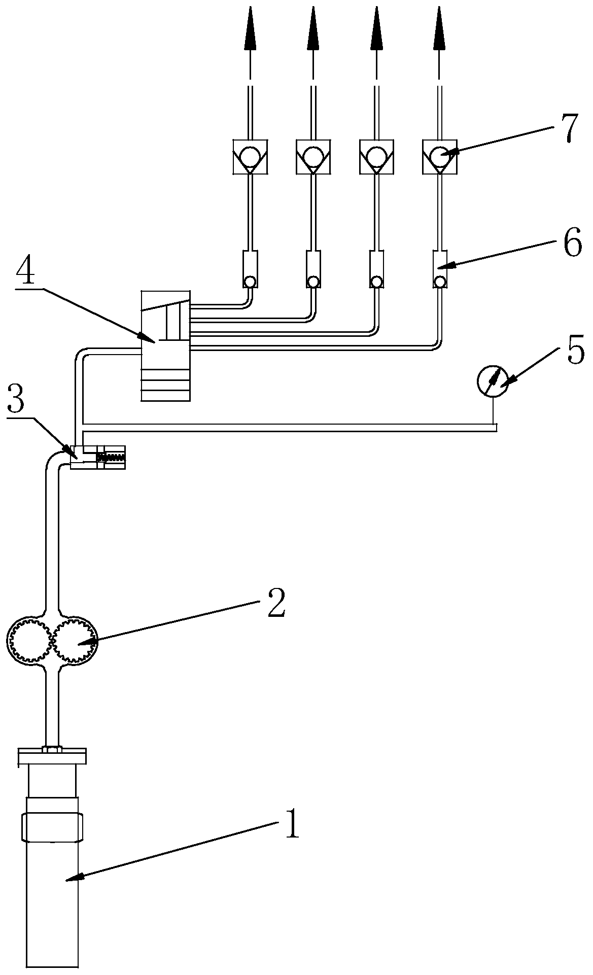
[0038] Such as figure 1 As shown, the compressor lubrication system includes a gear pump 2, an oil injector 4, a pressure limiting valve 3 and an oil filter 1; one end of the oil inlet of the oil filter 1 is connected below the liquid level of the oil tank; the gear pump 2 The oil inlet is connected with the oil outlet of the oil filter 1 through the oil passage, the oil outlet of the gear pump 2 is connected with the oil inlet of the pressure limiting valve 3 through the oil passage; the oil inlet of the oil injector 4 is connected through the The oil passage is connected with the oil outlet of the pressure limiting valve 3, and the lubricating oil derived from the oil outlet of the lubricator 4 enters the compressor through the passage.

Embodiment 2

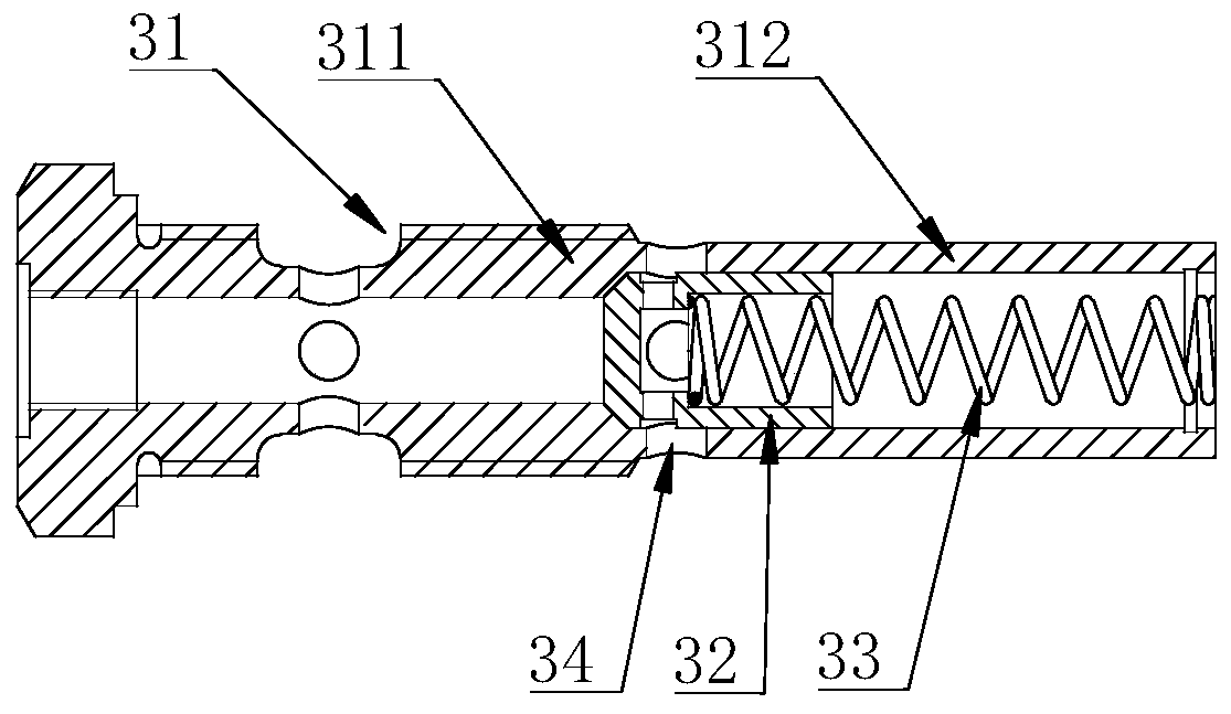
[0040] On the basis of Example 1, such as figure 2 As shown, the pressure limiting valve 3 includes a valve body 31, a limit piston 32 and an elastic device 33; the valve body 31 includes an integrated oil guide section 311 and an oil unloading section 312; the oil guide section 311 is provided with Conducting the first oil passage of the oil inlet and the oil outlet of the pressure limiting valve 3; the inside of the oil unloading section 312 is provided with a cavity, and the wall of the cavity is provided with a penetrating oil unloading port 34, and the inside of the cavity A limit piston 32 is provided; the limit piston 32 is arranged close to the oil guide section 311, and one end of the limit piston 32 away from the oil guide section 311 is provided for blocking the limit piston in the second position under the set oil pressure. In an oil passage, there is an elastic force device 33 for blocking the flow. When the internal pressure of the valve body 31 is lower than t...

Embodiment 3

[0042] On the basis of Embodiment 1, the compressor lubrication system also includes a pressure gauge 5, an oil sight glass 6 and a one-way valve 7; the one-way valve 7 is arranged between the oiler 4 and the compressor, and is used for 4 is one-way conduction in the direction of the compressor; the oil sight glass 6 is set between the oiler 4 and the one-way valve 7; the pressure gauge 5 is set between the pressure limiting valve 3 and the oiler 4.


PUM


Abstract

The invention relates to an oil injector, and relates to the technical field of oil injection devices. The oil injector comprises an oil injector housing, an oil injection plug circulating motion pushing member, an oil injection plug and a driving shaft, and the middle portion of the oil injector housing is provided with a spindle hole; the oil injector housing is provided with a piston hole; a piston hole at the bottom of the oil injection plug is a compression chamber; the oil injector housing is provided with an oil injector oil inlet and an oil injector oil outlet; the driving shaft is provided with an oil inlet passage for communicating the oil injector oil inlet with a circulation breakover oil injector oil outlet; when the oil injection plug circulating motion pushing member bringsthe oil injection plug to a high position, the oil inlet passage communicate with the oil injector oil outlet through the compression chamber; and when the oil injection plug circulating motion pushing member brings to the oil injection plug to a low position, the oil inlet passage is blocked from the compression chamber. By means of the oil injector, a worm wheel, a worm and a swash plate are used for converting rotation in the horizontal rotation into reciprocating linear motion in the vertical direction, and the oil injector has the characteristics of being compact in structure, reliable inuse, easy and convenient to maintain, adjustable in oil injection amount and capable of achieving self-protection.

Description

technical field [0001] The invention relates to the technical field of oil injection devices, in particular to an oil injection device. Background technique [0002] Piston-type high-pressure air compressors generally improve compression efficiency through multi-stage compression. Piston compressors change the internal volume of the cylinders by a group or groups of cylinders and reciprocating pistons in the cylinders. During the compression process, the high-pressure piston is generally lubricated by injecting oil between the piston and the cylinder liner through the oiler. Because the pressure of the high-pressure stage is generally high, the ordinary oiler needs to be driven by an external motor to complete the oil injection, which not only increases the cost, but also is prone to failure due to harsh working conditions, resulting in failure to supply oil in time and affecting the normal operation of the compressor. Contents of the invention [0003] In order to solve...

Claims


Application Information

Patent Timeline
Patent Type & Authority Applications(China)
IPC IPC(8): F04B39/02
CPCF04B39/02
Inventor 邢志胜耿茂飞金丽琼朱宝庆毛京兵任芳叶鹏李国强张志恒李金禄姜慧君
Owner HEFEI GENERAL MACHINERY RES INST
Why Eureka
Try Eureka