
Laser scanning anti-clamping system suitable for rail traffic station door and control method of laser scanning anti-clamping system

A technology of laser scanning and rail transit, which is applied in the direction of tracks, roads, stations, etc., can solve the problems of the stability of the detection system setting, the impact on the safety of train operation, the inability to fully guarantee the accuracy of detection, and the increase in station operating costs, etc., to achieve Reduce the generation of detection blind spots, improve the stability of settings, and improve the effect of operating safety

Active Publication Date: 2019-08-09
CHINA RAILWAY SIYUAN SURVEY & DESIGN GRP
View PDF7 Cites 3 Cited by
  • Summary
  • Abstract
  • Description
  • Claims
  • Application Information

AI Technical Summary

Problems solved by technology

However, due to the straight-forward nature of laser transmission, there is a certain blind spot in the detection of parallel laser beams, and the accuracy of detection cannot be fully guaranteed. In addition, the existing laser detection system often needs to invade the limit, so the setting of the detection system is stable. There is a certain impact on safety and train operation safety; at the same time, during the long-term use of the existing laser detection system, it usually displaces due to the vibration of the environment, resulting in a deviation in the alignment and reporting an error, which requires frequent manual repairs and maintenance. , increasing the operating cost of the station, causing great inconvenience

Method used


Image

  • Laser scanning anti-clamping system suitable for rail traffic station door and control method of laser scanning anti-clamping system
  • Laser scanning anti-clamping system suitable for rail traffic station door and control method of laser scanning anti-clamping system
  • Laser scanning anti-clamping system suitable for rail traffic station door and control method of laser scanning anti-clamping system

Examples


Embodiment Construction

[0042] In order to make the object, technical solution and advantages of the present invention clearer, the present invention will be further described in detail below in conjunction with the accompanying drawings and embodiments. It should be understood that the specific embodiments described here are only used to explain the present invention, not to limit the present invention.

[0043] In addition, the technical features involved in the various embodiments of the present invention described below can be combined with each other as long as they do not constitute a conflict with each other.

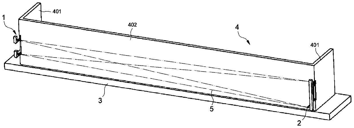
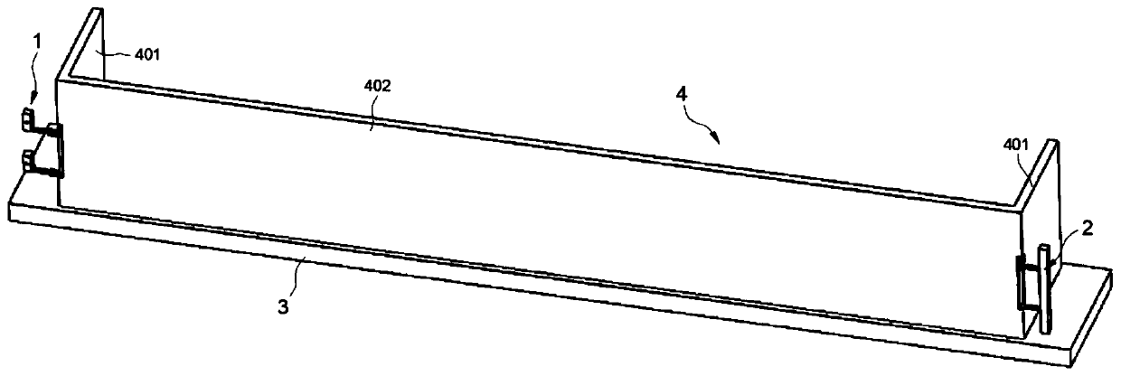
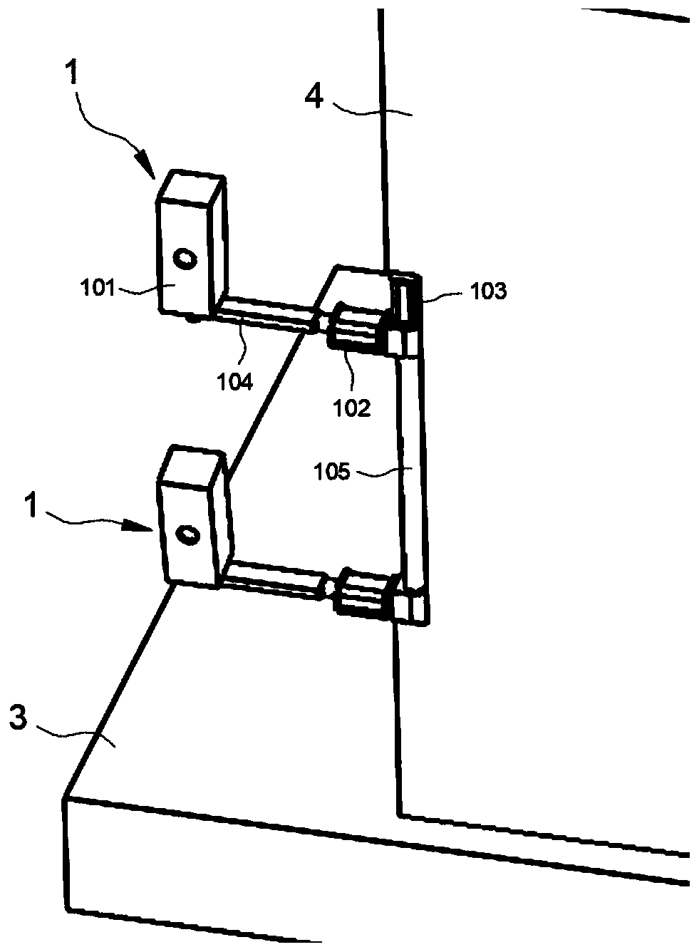
[0044] The laser scanning anti-pinch system in the preferred embodiment of the present invention is as figure 1 with 2 shown in , where, figure 1 A schematic diagram of the working state of the laser scanning anti-trap system, figure 2 It is a schematic diagram of the state when the laser scanning anti-pinch system is not working. It is not difficult to see from the diagram that th...


PUM


Abstract

The invention discloses a laser scanning anti-clamping system suitable for a rail traffic station door and a control method of the laser scanning anti-clamping system, and belongs to the technical field of station door security detection. End doors at the two ends of a station are provided with a laser scanning unit and a laser receiving unit correspondingly, a scanning steering engine, a rotatingmotor and a rotating shaft are correspondingly arranged, through control of corresponding rotating motor, an anti-clamping system extends into or be away from a train limit, and surface scanning detection of lasers is achieved through corresponding control of the scanning steering engine. According to the laser scanning anti-clamping system, the structure is simple, arrangement is simple and convenient, surface scanning detection of human or objects between a station door assembly and a train body can be effectively achieved, safety of station operation is ensured, precision of detecting is high, the error is small, the train limit is not invaded by the anti-clamping system during train operation, stability of train operation can be fully ensured, damage on the train body of the anti-clamping system is reduced, the service lift of the anti-clamping system is also long, and the laser scanning anti-clamping system has good application prospects and promotion value.

Description

technical field [0001] The invention belongs to the technical field of platform door safety detection, and in particular relates to a laser scanning anti-pinch system suitable for rail transit platform doors and a control method thereof. Background technique [0002] With the continuous acceleration of urbanization, the application of rail transit is becoming more and more common. Compared with other urban transportation systems, rail transit has a large capacity and high punctuality rate, which can greatly facilitate people's travel, and rail transit often does not occupy the road space of cars and buses, which is very important for improving urban congestion. significant effect. [0003] During the operation of rail transit, a platform door system is generally installed on the platform to separate the platform from the track and realize passengers' getting on and off. Due to the consideration of the train limit during the train operation, the setting of the platform door...

Claims


Application Information

Patent Timeline
Patent Type & Authority Applications(China)
IPC IPC(8): B61B1/02G01V8/26G01V8/18
CPCB61B1/02G01V8/26G01V8/18Y02T30/00
Inventor 何翔朱丹张浩刘辉张琨邱绍峰周明翔张俊岭郭文浩曹海峰
Owner CHINA RAILWAY SIYUAN SURVEY & DESIGN GRP
Learn More