Double-closing and double-opening plugging device

A technology of plug and nozzle core, which is applied in the field of layered water injection tools in oilfields, to achieve the effects of reducing workload, reducing nozzle damage and eliminating backlash gaps

Active Publication Date: 2019-08-09
CHINA PETROLEUM & CHEM CORP +2
View PDF5 Cites 2 Cited by
  • Summary
  • Abstract
  • Description
  • Claims
  • Application Information

AI Technical Summary

Problems solved by technology

For example, in the patent specification with the patent number of 2015200796938, an intelligent adjustable anti-return dead mouth plug is disclosed, which uses the gap between the valve core and the valve sleeve to control the flow, and the valve ball and the valve sleeve are combined to achieve closure; Nozzles are only improved in terms of their own performance, but not from the perspective of overall technology, so as to improve performance and reduce application costs

Method used


Image

  • Double-closing and double-opening plugging device
  • Double-closing and double-opening plugging device
  • Double-closing and double-opening plugging device

Examples


Embodiment 1

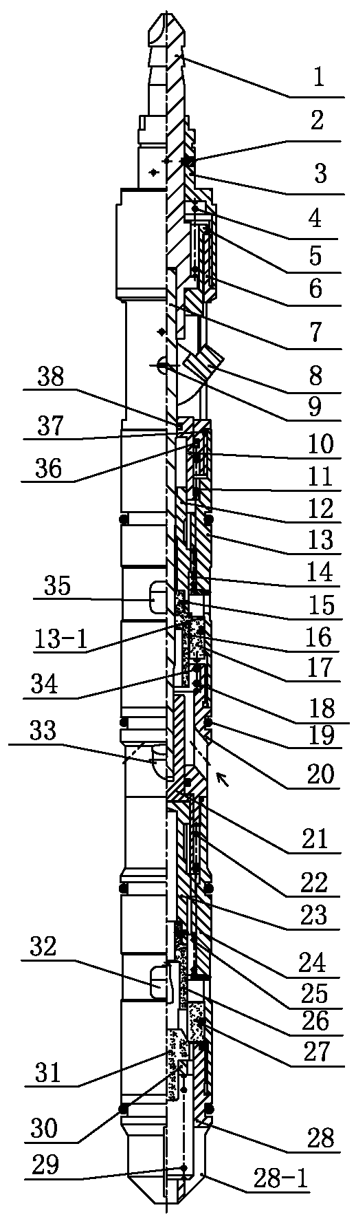
[0022] Such as figure 1 — image 3Shown is a double-closed double-open plug of this embodiment, including a salvage assembly, the main drive shaft 7 is slidably connected to the lower part of the salvage assembly, and an upper silk shell 13 is provided on the outer periphery of the middle part of the main drive shaft 7, and the lower part of the upper silk shell 13 is The middle shell 20 and the lower silk shell 24 are connected successively, the lower end of the lower silk shell 24 is connected with a lower pressure cap 28, the middle shell 20 is provided with an upper water inlet 20-1 circumferentially, the upper silk shell 13 is circumferentially provided with an upper water outlet 35, and the lower silk shell 24 The lower water outlet 32 ​​is arranged in the circumferential direction, the lower water inlet 28-1 is arranged in the lower pressure cap 28 circumferential direction, and the upper mouth cover 17 is provided for sliding sealing in the upper silk shell 13 on the l...

Embodiment 2

[0029] The difference between this embodiment and Embodiment 1 is that the structure of the valve assembly at the bottom of the lower mouth cover 27 is different, such as Figure 4 As shown, the valve assembly includes a ball valve 40 that abuts against the matching taper surface at the lower end of the lower mouth cover 27. The lower part of the ball valve 40 is provided with a ball holder 39, and an axial pressure is provided between the ball holder 39 and the lower pressure cap 28. Tight spring 29, the circumferential direction that ball valve 40 and ball holder 39 cooperate with pressing down cap 28 are provided with the passage that communicates with the water inlet passage of bottom. In this structure, the lower water nozzle is closed through the sealing cooperation between the ball valve 40 and the cone valve port of the lower mouth cover 27. When the lower nozzle core axis moves downward to push the ball valve open, the water inlet channel of the lower nozzle core is op...

Embodiment 3

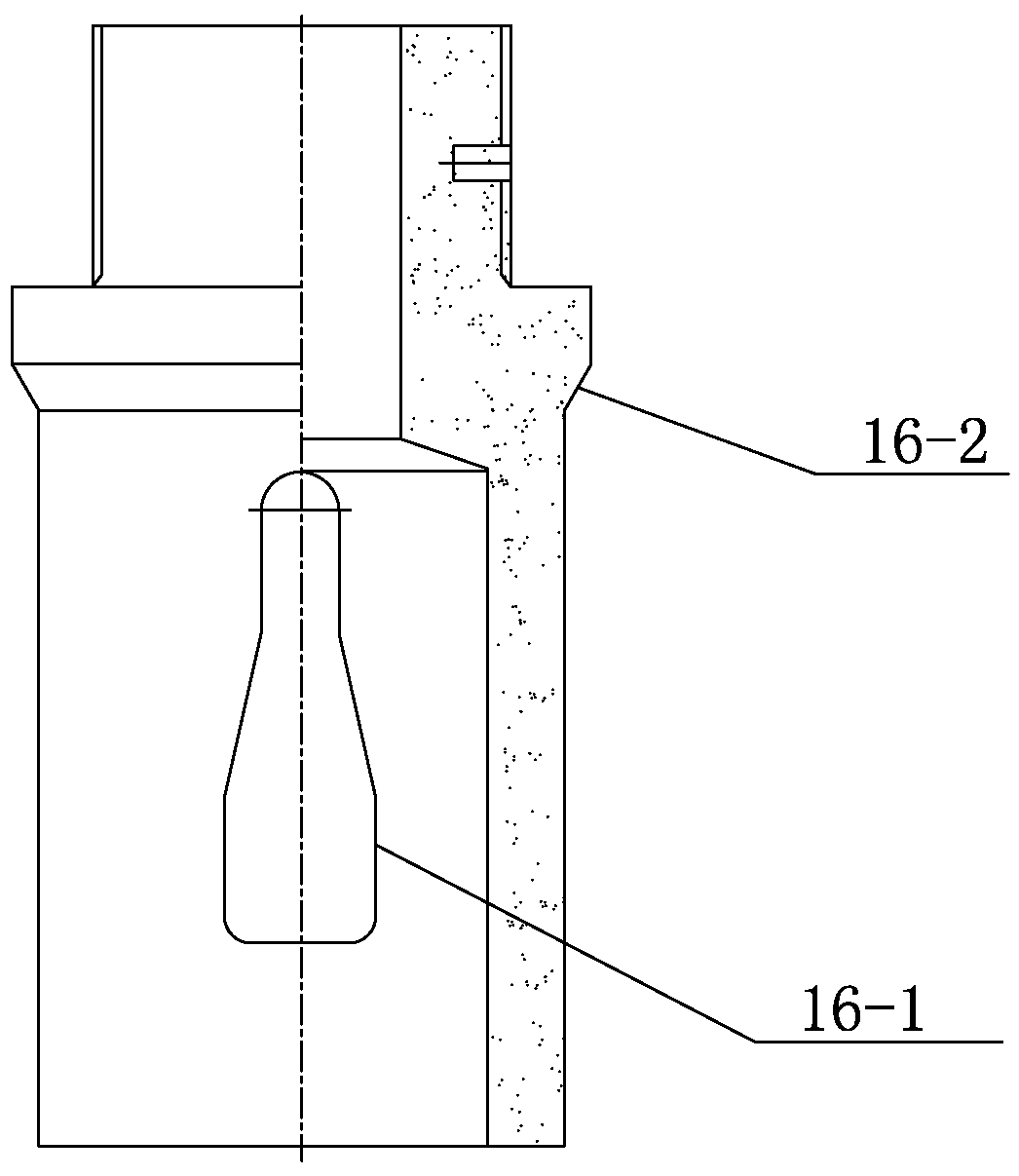
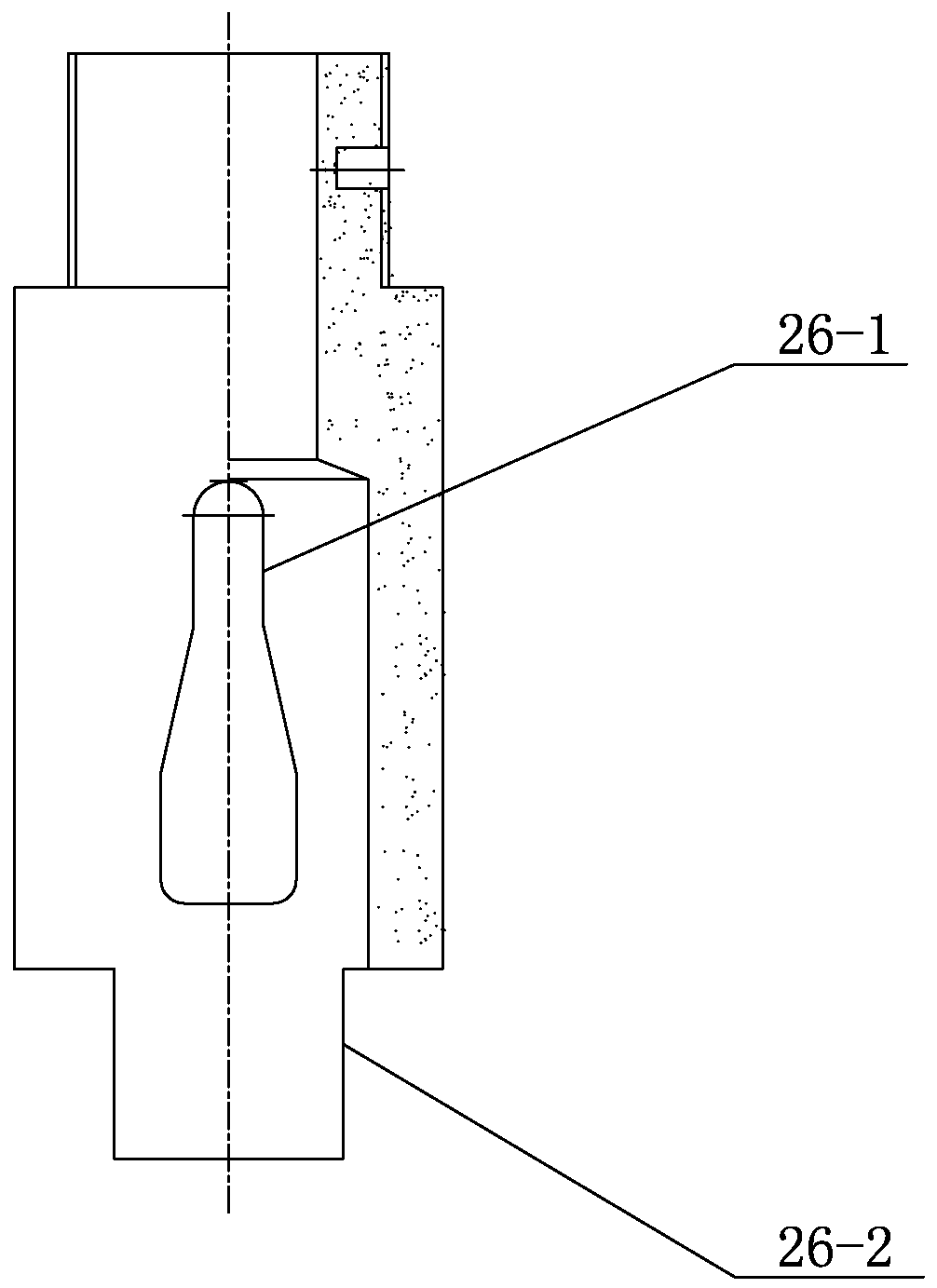
[0031] Such as figure 1 , Figure 5 Shown is a double-closed double-open plug of this embodiment, the spring 29, the cone sleeve 30, and the cone valve 31 are removed; the lower mouthpiece adopts the same structure as the upper mouthpiece; the upper mouthpiece 16 and the lower mouthpiece 26 are set at the same time It is in a fully open state, and the direction of the bottle-shaped water outlet of the upper mouth core is the bottle mouth upward, and the direction of the bottle-shaped water outlet of the lower mouth core is the bottle mouth downward. The direction of rotation of the internal transmission threads is the same; when the main drive shaft 7 rotates, the upper nozzle core 16 and the lower nozzle core 26 are driven downward at the same time. Since the direction of the water outlet 16-3 is opposite to that of the water outlet 26-1, the water outlet 16-3 is slowly closed. , The water outlet 26-1 is quickly closed, realizing the synchronous control of the water volume o...


PUM


Abstract

The invention relates to a double-closing and double-opening plugging device in the field of oil field layered water injection tools. The double-closing and double-opening plugging device comprises anupper spout sleeve which is arranged in an upper screw shell in a floating sealed mode; the upper end of the upper spout sleeve is provided with a limiting step, and the lower end of the upper spoutsleeve abuts against a reset spring; an upper spout core is arranged in the upper spout sleeve, and the upper spout core and the upper spout sleeve are in sliding clearance fit in the circumferentialdirection; a radial water outlet is formed in the circumferential direction of the upper spout core, and the upper side, matched with the upper spout core, of the upper spout sleeve is provided with asealed conical surface in a matched mode in the circumferential direction; the upper part of the upper spout core is connected with an upper screw shaft, the upper screw shaft is inserted in the outer circumference of a main driving shaft in an axial sliding mode, and the outer circumference of the upper screw shaft is in threaded transmission connection with the upper screw shell; a lower spoutsleeve is fixedly arranged in a lower screw shell of the main driving shaft part, the inner circumference of the lower spout sleeve is provided with a lower spout core in a matched mode, a radial water outlet is formed in the circumferential direction of the lower spout core, and the upper part of the lower spout core is connected with a lower screw shaft in a rotation following mode; and the lower screw shaft is connected with the main driving shaft through a lower driving sleeve in a rotation following mode, the outer circumference of the lower screw shaft is in threaded transmission connection with the lower screw shell, the inner circumference of the lower part of the lower spout sleeve is provided with a matched conical surface, and the lower side of the lower spout sleeve is providedwith a cone valve assembly abutting against the matched conical surface in a matched mode.

Description

technical field [0001] The invention relates to the field of layered water injection tools for oil fields, in particular to a double-closed and double-opened plug used for sealing off water distributors and capable of synchronously measuring and distributing water in two layers. Background technique [0002] The newly developed eccentric integrated packing water distributor in other domestic oilfields has two types of plugs: ①integrated plug, when the packer is seated, two dead nozzles are installed first, and two water nozzles are built in after the packer is picked up. The size of the plug is fixed. When adjusting, it needs to be pulled out from the well and put in again. The workload is heavy. When testing and deploying, a storage type flowmeter is used, and the data needs to be played back on the ground. With the increase of the number of layers, the measurement and adjustment period is prolonged, and the production cost and labor intensity are increased. Two single-la...

Claims


Application Information

Patent Timeline
Patent Type & Authority Applications(China)
IPC IPC(8): E21B43/20E21B34/14E21B33/12E21B31/00
CPCE21B31/00E21B33/1208E21B34/14E21B43/20
Inventor 石建设石易蕾彭太祥李汉周
Owner CHINA PETROLEUM & CHEM CORP
Why Eureka
Try Eureka