Vapor chamber with supporting pillar and groove composite structure

A composite structure and support column technology, applied in lighting and heating equipment, indirect heat exchangers, modification by conduction heat transfer, etc., can solve the problems of rapid backflow of unfavorable working fluid, influence of heat transfer performance, limited capillary pressure, etc. Achieve the effect of improving the maximum working power, ensuring the strength, and promoting full evaporation

Inactive Publication Date: 2019-08-09
SOUTH CHINA UNIV OF TECH
View PDF2 Cites 10 Cited by
  • Summary
  • Abstract
  • Description
  • Claims
  • Application Information

AI Technical Summary

Problems solved by technology

[0004] CN 102706193A discloses a radial gradually widening fin structure grooved flat heat pipe and its processing method, including a lower base, an upper cover plate and a support ring, the lower base includes a circular base, and there is a circular base on the circular base The top surface of the boss is an inner conical slope with a low center and high outer edge, and V-shaped grooves and ridges are radially distributed from the center to the outside, but the flat heat pipe is only provided with a capillary on the top surface of the boss. The core structure, the groove part is plowed, which will cause insufficient capillary pressure; at the same time, the groove structure is relatively compact, which is not conducive to the full evaporation of the working fluid, and the heat transfer performance is affected
[0005] CN 104534906A discloses a flat heat pipe with a nested porous liquid-absorbing core structure and its manufacturing method. The upper and lower metal cover plates form a closed cavity, and the evaporation surface is processed with sintered porous columns with inner grooves arranged in an array , the condensing surface is processed with porous protrusions matching the groove, and the two are closely matched to form a porous structure column, but only the sintered porous column of the flat heat pipe can provide the condensation return channel, and no continuous channel is formed, which is not conducive to the rapid cooling of the working medium. Backflow, and the capillary pressure provided by the sintered column is limited, which will affect the improvement of heat transfer performance

Method used


Image

  • Vapor chamber with supporting pillar and groove composite structure
  • Vapor chamber with supporting pillar and groove composite structure
  • Vapor chamber with supporting pillar and groove composite structure

Examples


Embodiment Construction

[0038] The present invention will be described in further detail below in conjunction with the accompanying drawings and specific examples, but the embodiments of the present invention are not limited thereto, and for process parameters not specifically indicated, reference may be made to conventional techniques.

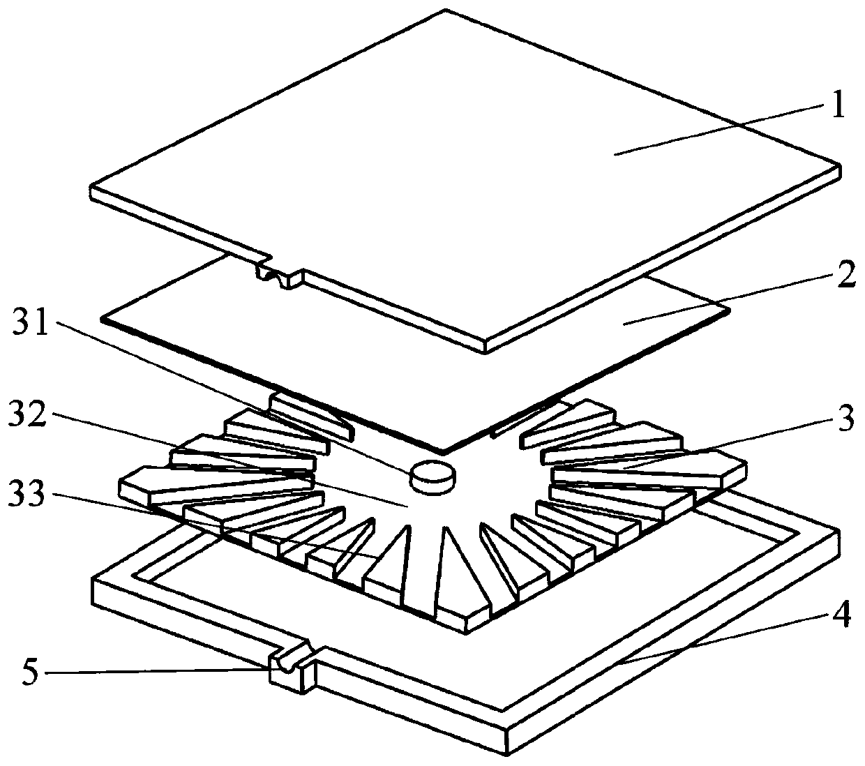
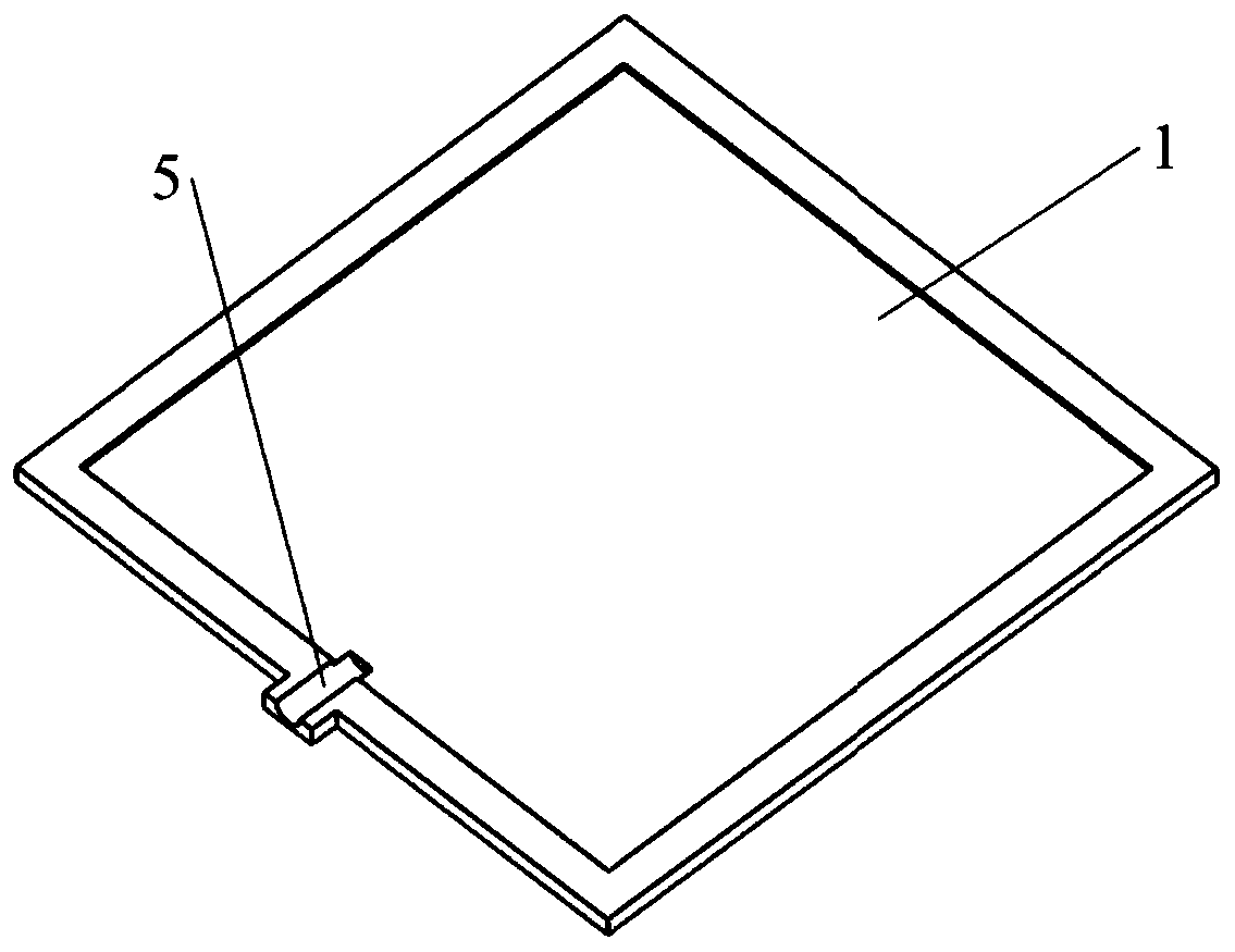
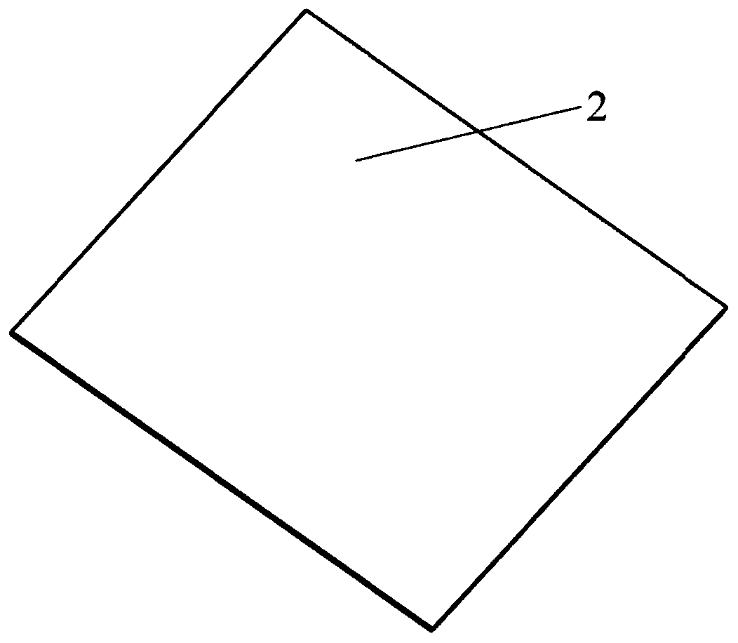
[0039] like figure 1 As shown, a vapor chamber with a support column and a groove composite structure includes an upper cover 1 and a lower cover 4, such as Figure 2-3 As shown in and 6, a condensing end liquid-absorbing core 2 is sintered in the cavity in the upper cover plate 1, such as Figure 4-5 As shown in and 7, the evaporating end liquid-absorbing core 3 is sintered in the cavity in the lower cover plate 4; there is an annular cavity 32 in the middle of the evaporating end liquid-absorbing core structure, and a support column 31 is arranged in the center of the annular cavity 32, and the hollow The outer circumference of the cavity is an equidistant groove...


PUM


Abstract

The invention discloses a vapor chamber with a supporting pillar and a groove composite structure. The vapor chamber comprises an upper covering plate and a lower covering plate, wherein a condensation end liquid suction core is disposed in a cavity of the upper covering plate; an evaporation end liquid suction core is disposed in a cavity of the lower covering plate; an annular cavity is disposedin the evaporation end liquid suction core; a supporting pillar is disposed at the center of the annular cavity; a groove structure is disposed in peripheries of the annular cavity; both the supporting pillar and the groove structure get contacted with the condensation end liquid suction core; and the upper covering plate and the lower covering plate are sealed, and a liquid filling hole is formed between the upper covering plate and the lower covering plate. Evaporation of a liquid working medium and collection of a condensation liquid are promoted by the cavity of the evaporation end liquidsuction core, and a liquid backflow channel is formed by the supporting pillar to reduce a pressure drop at the center; evaporation of the liquid working medium and backflow of the working medium toa center evaporation area are promoted by the cavity of the groove, so heat transfer performance is improved; a main backflow channel of the condensation liquid is formed by an entity part of the groove, so condensation and backflow are accelerated; and strength of the vapor chamber is ensured by the supporting pillar and the groove structure, so collapse and thermal deformation of the vapor chamber are avoided effectively.

Description

technical field [0001] The invention designs a soaking plate for heat dissipation of a photoelectric device, and in particular relates to a soaking plate with a composite structure of supporting columns and grooves. Background technique [0002] With the rapid development of microelectronics technology, telecommunication industry and energy fields, various high heat flux devices, such as CPU, GPU, high intensity light emitting diode (LED) and solar cells, etc. At the same time, it also leads to the problem of heat dissipation of high heat flow and high-power chips in a limited heat dissipation space. The performance of electronic components is very sensitive to temperature. Excessively high temperature will have a significant impact on the performance of components, and even affect the normal operation of the entire system. However, traditional cooling methods can no longer meet the heat dissipation requirements of modern high-heat flow electronic components, so new heat di...

Claims


Application Information

Patent Timeline
Patent Type & Authority Applications(China)
IPC IPC(8): F28D15/04H05K7/20
CPCF28D15/043H05K7/20509
Inventor 徐志佳赵豪王清辉李静蓉邓大祥
Owner SOUTH CHINA UNIV OF TECH
Why Eureka
Try Eureka