Method, device and storage medium for evaluating peripheral edge wear of cylindrical vertical milling cutter

An evaluation method, vertical milling technology, applied in image analysis, image enhancement, instruments, etc., can solve problems such as the height VB of the wear zone on the knife face and its area, and principle errors

Active Publication Date: 2021-01-22
XIAMEN UNIV OF TECH
View PDF9 Cites 0 Cited by
  • Summary
  • Abstract
  • Description
  • Claims
  • Application Information

AI Technical Summary

Problems solved by technology

However, since the peripheral edge of the cylindrical vertical milling cutter has a helical surface structure, general-purpose equipment or instruments are used for measurement, and there are no special process equipment or auxiliary tools to be used with it. The face wear zone height VB and its area are extremely difficult
It is not difficult to find that there is a principle error in the previous direct detection method

Method used


Image

  • Method, device and storage medium for evaluating peripheral edge wear of cylindrical vertical milling cutter
  • Method, device and storage medium for evaluating peripheral edge wear of cylindrical vertical milling cutter
  • Method, device and storage medium for evaluating peripheral edge wear of cylindrical vertical milling cutter

Examples


no. 1 example

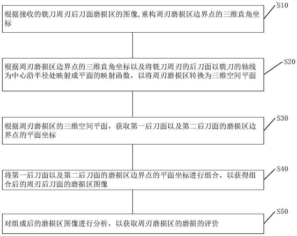
[0066] see Figure 1 to Figure 14 , the embodiment of the present invention provides a method for evaluating the peripheral edge wear of a cylindrical vertical milling cutter, including:

[0067] S10, reconstructing the three-dimensional Cartesian coordinates of boundary points of the flank wear area of ​​the milling cutter according to the received image of the flank wear area of ​​the milling cutter.

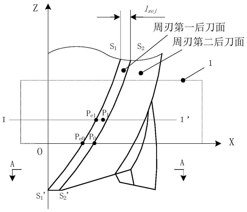
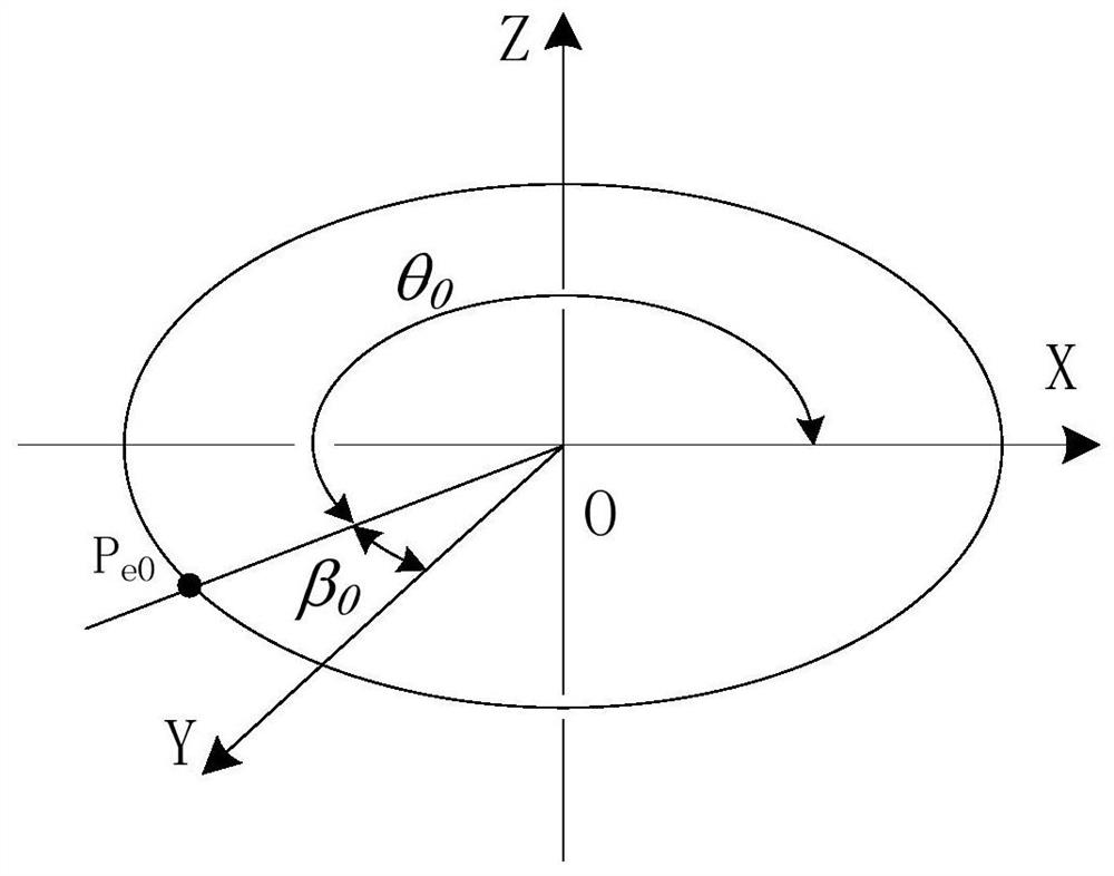
[0068] In the present embodiment, according to the images received by the video microscope, a rectangular area 1 is constructed with sides perpendicular to the axis of the milling cutter and covering the wear zone (see figure 2 ). First, take the tool axis as the Z axis, and the rectangular side (near the bottom edge) as the X axis to establish a rectangular coordinate system, and the X axis and the helical line S at the top of the peripheral cutting edge 1 S 1 ', helix line S at the bottom of the peripheral edge 2 S 2 'respectively handed over to P e0 and P 0 Point, w...

no. 2 example

[0111] The second embodiment of the present invention provides a peripheral edge wear evaluation device for a cylindrical vertical milling cutter, including:

[0112] The three-dimensional Cartesian coordinate reconstruction unit 100 is used to reconstruct the three-dimensional Cartesian coordinates of the boundary points of the peripheral edge wear zone according to the received image of the flank wear zone of the peripheral edge of the milling cutter;

[0113] The three-dimensional space plane reconstruction unit 200 is used to map the flank of the peripheral edge of the milling cutter into a plane along the radius with the axis of the milling cutter as the center according to the three-dimensional Cartesian coordinates of the boundary points of the wear zone of the peripheral edge The mapping function, to convert the wear area of ​​the peripheral edge into a three-dimensional space plane;

[0114] The acquisition unit 300 is configured to acquire the plane coordinates of th...

no. 4 example

[0134] The present invention provides a peripheral edge wear evaluation device of a cylindrical vertical milling cutter, comprising a processor, a memory, and a computer program stored in the memory and configured to be executed by the processing, when the processor executes the computer program Realize the method for evaluating the peripheral edge wear of a cylindrical vertical milling cutter as described in any one of the above-mentioned embodiments.

[0135] Exemplarily, the computer program described in the fourth embodiment of the present invention can be divided into one or more modules, and the one or more modules are stored in the memory and executed by the processor to Complete the present invention. The one or more modules may be a series of computer program instruction segments capable of accomplishing specific functions, and the instruction segments are used to describe the execution process of the computer program in the implementation server device. For example,...


PUM


Abstract

The invention discloses a cylindrical vertical milling cutter peripheral edge wear evaluation method and device and a storage medium, and the method comprises the steps: reconstructing a three-dimensional rectangular coordinate of a peripheral edge wear area boundary point according to a received image of a milling cutter peripheral edge rear cutter surface wear area; according to the three-dimensional rectangular coordinate of the boundary point of the peripheral edge wear area and a mapping function for mapping the flank surface of the peripheral edge of the milling cutter into a plane alongthe radius by taking the axis of the milling cutter as the center, converting the peripheral edge wear area into a three-dimensional space plane; according to the three-dimensional space plane of theperipheral edge abrasion area, obtaining plane coordinates of abrasion area boundary points of the first rear cutter face and the second rear cutter face; combining the wear areas of the first flanksurface and the second flank surface to obtain a combined wear area image of the peripheral edge flank surface; and analyzing the formed wear region image to obtain the evaluation of the wear of the peripheral edge wear region. By analyzing the reconstructed wear area, the evaluation of the wear of the peripheral edge of the milling cutter is realized.

Description

technical field [0001] The invention relates to the application field of mechanical processing technology, in particular to a method, device and storage medium for evaluating the wear of a peripheral edge of a cylindrical vertical milling cutter. Background technique [0002] In the process of metal cutting, tool wear is an important factor affecting the processing quality, production efficiency and manufacturing cost of parts. In order to detect tool wear in the cutting process, researchers have proposed a variety of wear detection methods, which are mainly divided into two categories, direct detection method and indirect detection method. Direct detection methods usually include contact measurement method and video image measurement method; indirect detection method is to obtain the wear amount of the tool through the change of relevant physical quantities in the processing environment. Obviously, the indirect detection method is also realized by the direct detection meth...

Claims


Application Information

Patent Timeline
Patent Type & Authority Patents(China)
IPC IPC(8): G06T7/00G06T17/00
CPCG06T7/0002G06T17/00G06T2207/30164
Inventor 盛精姚丽萍
Owner XIAMEN UNIV OF TECH
Why Eureka
Try Eureka