Displacement temporary storage device

A technology of displacement temporary storage and transistor, applied in information storage, static memory, digital memory information and other directions, can solve the problems of easy failure of components and inability to have operating frequency at the same time, and achieve the effect of increasing reliability.

Inactive Publication Date: 2019-08-09
CHUNGHWA PICTURE TUBES LTD
View PDF10 Cites 0 Cited by
  • Summary
  • Abstract
  • Description
  • Claims
  • Application Information

AI Technical Summary

Problems solved by technology

In the design, the operating frequency with better touch sensitivity is usually given priority. However, the disadvantage of this operating frequency is that the components are prone to failure during long-term reliable operation (high-temperature operation or high-temperature and high-humidity operation). The design of the known gate drive array (GOA) circuit cannot have the selectivity of different operating frequencies at the same time

Method used


Image

  • Displacement temporary storage device
  • Displacement temporary storage device
  • Displacement temporary storage device

Examples


Embodiment Construction

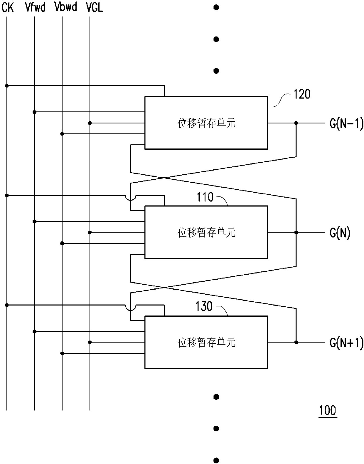
[0045] Please refer to figure 1 , figure 1 A schematic diagram showing a displacement temporary storage device according to an embodiment of the present invention. The displacement temporary storage device 100 includes a plurality of displacement temporary storage units 110, 120, 130. To simplify the description, this embodiment only shows the displacement temporary storage units 120, 110, 130 of the N-1st to N+1th stages. Where N is a positive integer. Taking the shift register unit 110 of the Nth stage as an example, the shift register unit 110 receives the output signal G(N-1) of the N-1 stage, the clock signal CK, the first voltage Vfwd, the second voltage Vbwd, the Nth stage The +1 stage outputs the signal G(N+1) and the gate low voltage VGL to generate the output signal G(N). Wherein, the shift register unit 110 generates an output signal G(N) having the same voltage level as the clock signal CK according to the first voltage Vfwd. And according to the second voltage...


PUM


Abstract

A displacement temporary storage device comprises a plurality of displacement temporary storage units. The displacement temporary storage units are serially connected and coupled. An N-th stage of displacement temporary storage unit comprises a voltage setting circuit, at least two control signal generators, at least two backup control signal generators and an output stage circuit. The at least two backup control signal generators are coupled to the first control end and the second control end, and the at least two backup control signal generators respectively receive at least two backup biasvoltages and respectively generate a first control voltage and a second control voltage according to the at least two backup bias voltages.

Description

technical field [0001] The invention relates to a displacement temporary storage device, in particular to a selective displacement temporary storage device with different operating frequencies. Background technique [0002] In recent years, with the vigorous development of semiconductor technology, portable electronic products and flat panel display products are also emerging. Among many types of flat panel displays, Liquid Crystal Display (LCD) has become the mainstream of various display products due to its advantages of low voltage operation, no radiation scattering, light weight and small size. Also because of this, all the manufacturers are driving the development technology of liquid crystal display toward more miniaturization and low production cost. [0003] And in order to lower the production cost of liquid crystal displays, some manufacturers have proposed to use thin film transistors (thin film transistor, TFT) directly on the glass substrate to make a multi-lev...

Claims


Application Information

Patent Timeline
Patent Type & Authority Applications(China)
IPC IPC(8): G11C19/28G09G3/36
CPCG09G3/3674G09G2310/0286G11C19/28G11C19/287G11C19/188
Inventor 林于胜宋伟廉
Owner CHUNGHWA PICTURE TUBES LTD
Why Eureka
Try Eureka