
Casting die machining equipment

A technology for processing equipment and casting molds, applied in metal processing equipment, manufacturing tools, grinding/polishing equipment, etc., can solve problems such as harsh working environment, low linkage, and difficulty in replacing abrasive belts

Active Publication Date: 2019-08-13
HUANGHUA RONGTAI MOLD
View PDF10 Cites 2 Cited by
  • Summary
  • Abstract
  • Description
  • Claims
  • Application Information

AI Technical Summary

Problems solved by technology

[0002] During the casting process, the mold after casting needs to be ground with burrs so that the mold can fit better. During the grinding process, more dust will be generated due to grinding, and more dust will remain on the outer surface of the grinding belt of the grinding machine. There are too many dust particles, and the dust particles are only released into the air during the grinding process, which will increase the density of the particles in the grinding environment, making the working environment of the personnel worse, which is not conducive to the operation of the personnel, and the internal linkage of general grinding equipment It is difficult to replace the grinding belt or the grinding wheel, and it takes a lot of force to disassemble the tool, which greatly increases the time for replacing related parts in the equipment, and makes the equipment more stable. The practicability is reduced. During the grinding process, it is not convenient for the personnel to hold the equipment to bear the force, so that the equipment cannot achieve better work when it is working. The grinding effect is reduced and the possibility of fragmentation of the grinding belt or grinding disc is increased, which greatly Affecting the safety of personnel's work

Method used


Image

  • Casting die machining equipment
  • Casting die machining equipment
  • Casting die machining equipment

Examples


Embodiment Construction

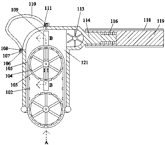
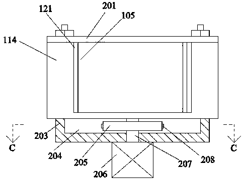
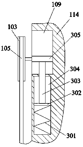
[0021] like Figure 1-Figure 4 As shown in the figure, the present invention will be described in detail. For the convenience of description, the orientations mentioned below are now defined as follows: figure 1 The projection relationship itself has the same direction of up, down, left, right, front, and back. A casting mold processing equipment of the present invention includes a transmission box 114. The right side of the outer surface of the transmission box 114 is provided with a handle device for convenient use by personnel. The transmission box 114 is provided with an accommodating cavity 121 with an opening facing downward, the left end wall of the accommodating cavity 121 communicates with a penetration cavity 111 with an opening, and a cloth bag device for receiving dust is provided at the outer position of the penetration cavity 111 , the accommodating cavity 121 is provided with a polishing device for grinding and is convenient for blowing the dust out to the cloth...


PUM


Abstract

The invention discloses casting die machining equipment. A transmission box is included. A grip device facilitating personnel to hold for usage is arranged on the right side of the outer surface of the transmission box. A containing cavity with a downward opening is formed in the transmission box. The left end wall of the containing cavity internally communicates with a penetration cavity with anopening. The outer side position of the penetration cavity is provided with a cloth bag device for receiving dust. The containing cavity is internally provided with a grinding device which is used forgrinding and conveniently blowing out dust to a cloth bag. The equipment is simple in structure, the grip device, the cloth bag device and the grinding device are adopted in the equipment, the personnel can better hold the equipment for usage, and the cloth bag device is utilized for centralized collection of surplus dust generated after grinding; and through the grinding device, efficient grinding is achieved, dust obtained after grinding can be blown and guided, and the particle density in the personnel operation area is reduced.

Description

technical field [0001] The invention relates to the technical field of casting, in particular to a casting mold processing equipment. Background technique [0002] In the casting process, the mold after casting needs to be polished with burrs so that the mold can fit better. There are many dust particles, and the dust particles are only released into the air during the grinding process, which will increase the particle density in the grinding environment, make the working environment of the personnel worse, and it is not conducive to the operation of the personnel, and the internal linkage of the general grinding equipment It is difficult to replace the abrasive belt or grinding wheel, and it takes a lot of force to remove the tool, which greatly improves the replacement time of the relevant parts in the equipment, and makes the equipment more durable. The practicability is reduced. During the grinding process, it is inconvenient for personnel to hold the equipment, so that...

Claims


Application Information

Patent Timeline
IPC IPC(8): B24B19/20B24B21/00B24B21/18B24B9/04B24B55/08
CPCB24B9/04B24B19/20B24B21/006B24B21/18B24B55/08
Inventor 不公告发明人
Owner HUANGHUA RONGTAI MOLD
Learn More