
Floor common formwork removing pre-buried part assembly and manufacturing and mounting construction methods thereof

A technology of embedded parts and formwork, which is applied in the field preparation of building components, processing of formwork, construction, etc., can solve the problems of slow formwork removal, slow work efficiency, and large safety hazards, and achieve high applicability, The effect of fast and easy demolition

Pending Publication Date: 2019-08-13
广西建工第五建筑工程集团有限公司
View PDF0 Cites 0 Cited by
  • Summary
  • Abstract
  • Description
  • Claims
  • Application Information

AI Technical Summary

Problems solved by technology

[0002] When the main floor of the current building is constructed with wooden formwork, it is mostly assembled directly; when the concrete of the floor slab reaches the conditions for formwork removal, the demolition workers can only use a crowbar to chisel into the joints between the wooden formwork and the wooden formwork little by little. The joints between the concrete floor and the concrete floor can be removed slowly, the work efficiency is slow, and the safety hazard is great
If the floor is high, the demolition workers need to use the operating platform to remove the slab formwork. The demolition speed is not only slow, but also the workers standing on the operating frame are more dangerous, because they have nowhere to hide and are easy to be dismantled template smashed

Method used


Image

  • Floor common formwork removing pre-buried part assembly and manufacturing and mounting construction methods thereof
  • Floor common formwork removing pre-buried part assembly and manufacturing and mounting construction methods thereof
  • Floor common formwork removing pre-buried part assembly and manufacturing and mounting construction methods thereof

Examples


Embodiment 1

[0077] A common formwork demoulding embedded part assembly for "ten" joints Ⅰ:

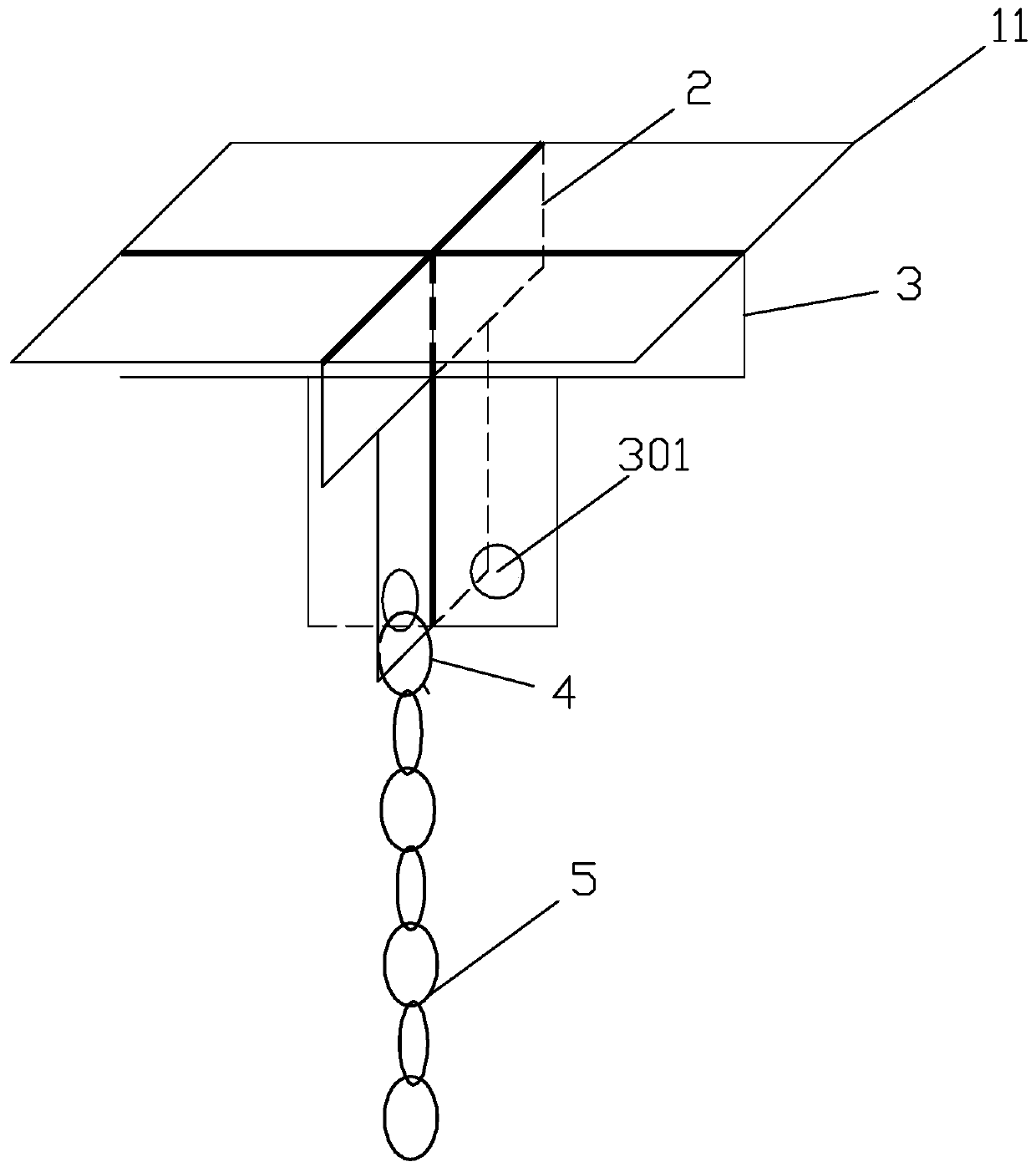
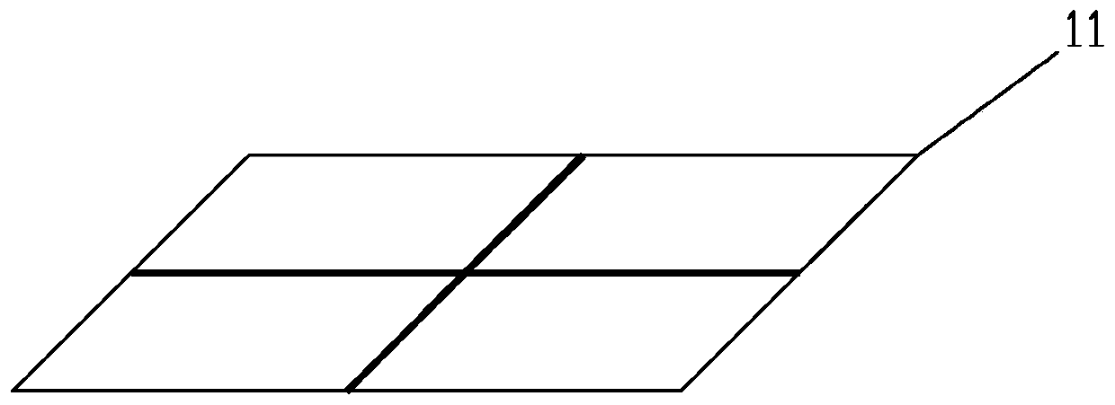
[0078] Such as figure 1 As shown, the general formwork demoulding embedded part assembly I for the "ten" joint of the floor includes a square top cover plate I11, a curb plate I2, a curb plate II3, a connecting movable buckle 4 and a retractable zipper 5;

[0079] The embedded part assembly I of the ordinary formwork demolition embedded part assembly I for the "ten" joint is composed of the top cover plate I11 with the top cover plate 1 as a square and the slab I2 and the two sides of the slab I2. The slab II3 is fixedly connected to form the embedded parts of the cross-shaped floor common formwork demoulding embedded parts assembly;

[0080] The square top cover plate I11 is a square plate surrounded by a hypotenuse with a width of 3-10mm, the slope of the hypotenuse α, that is, the angle between the hypotenuse of the top cover plate and the horizontal plane is 30°-60° (see diagram 2-1 , Fig...

Embodiment 2

[0085] A common formwork demoulding embedded part assembly for T-joint II:

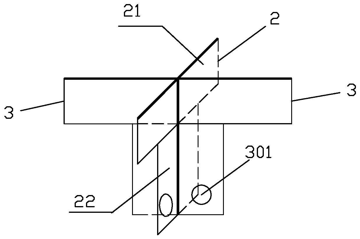
[0086] Such as image 3 As shown, the general formwork demoulding embedded part assembly II for the T-shaped joint includes a rectangular top cover plate II12, a stretching plate I2, a stretching plate II3, a connecting movable buckle 4 and a retractable zipper 5;

[0087] There is a hypotenuse with a width of about 3 to 10 mm around the rectangular top cover plate II12, and the slope α of the hypotenuse, that is, the angle between the hypotenuse of the top cover plate and the horizontal plane is 30° to 60°, (see Pic 4-1 and Figure 12 ,which is Figure 10 C-C cross-sectional view);

[0088] The embedded part component II of the ordinary formwork demoulding embedded part assembly II for the T-shaped joint is fixedly connected with the rectangular top cover plate II12, the drawn plate I2 and the drawn plate II3 located on one side of the drawn plate I2, forming The skeleton of the T-shaped embedde...

Embodiment 3

[0094] The invention discloses a method for manufacturing, installing and constructing a common formwork demoulding embedded part assembly of a floor slab.

[0095] It is a general formwork demoulding and embedded part assembly for "ten" joints described in the first embodiment and a common formwork demoulding and embedded part assembly for T-shaped joints described in the second embodiment. The method of installation and production;

[0096] It is made by connecting steel plate or aluminum formwork or iron plate or ABS hard material with a certain thickness (material with a thickness of about 1 to 3mm) and other materials that can achieve the strength required for demolition; according to the design drawing, it is connected by fixed connection. The embedded parts of a general formwork removal embedded part assembly of the floor slab are pre-embedded at the cross or right-angled side of the formwork after the splicing is completed; After the support system of the formwork is ...


PUM


Abstract

The invention provides a floor common formwork removing pre-buried part assembly. The floor common formwork removing pre-buried part assembly comprises a pre-buried part and a formwork removing part,wherein the pre-buried part is composed of a top cover plate, a rib plate I and a rib plate II, and the formwork removing part is composed of a connection movable buckle and a retractable zipper; thetop cover plate is a square plate, bevel edges with the width being 3-10 mm are arranged around the top cover plate, and the included angle between each bevel edge and the horizontal plane is alpha; the rib plate I is a T-shaped plate formed by a rectangular horizontal face plate I and a vertical plate I perpendicular to the rectangular horizontal face plate I in a fixedly connected mode, the ribplate II is a right-angled plate formed by a rectangular horizontal face plate II and a vertical plate II perpendicular to one side of the rectangular horizontal face plate II, a connecting hole I isformed in the lower part of the vertical plate I, and a connecting hole II is formed in the lower part of the vertical plate II; and the top cover plate, the rib plate I and the rib plate II are connected in a welded mode to form the pre-buried part, and the retractable zipper is connected with the rib plate I or the rib plate II through the connection movable buckle. By using the floor common formwork removing pre-buried part assembly, the formwork removing speed is high, and manufacturing and mounting construction methods of the floor common formwork removing pre-buried part assembly are efficient, environmentally friendly and safe.

Description

technical field [0001] The invention relates to auxiliary construction components in the technical field of building construction and a construction method thereof, in particular to a common formwork demoulding pre-embedded part assembly for all building floors and a construction method thereof. Background technique [0002] When the main floor of the current building is constructed with wooden formwork, it is mostly assembled directly; when the concrete of the floor slab reaches the conditions for formwork removal, the demolition workers can only use a crowbar to chisel into the joints between the wooden formwork and the wooden formwork little by little. The joints between the concrete floor and the concrete floor can be slowly removed. The work efficiency is slow and the safety hazard is great. If the floor is high, the demolition workers need to use the operating platform to remove the slab formwork. The demolition speed is not only slow, but also the workers standing on ...

Claims


Application Information

Patent Timeline
Patent Type & Authority Applications(China)
IPC IPC(8): E04G19/00E04G21/00
CPCE04G19/00E04G21/00
Inventor 王浩丁铁军高志鹏姜海洋莫丽萍施灿麟
Owner 广西建工第五建筑工程集团有限公司
Learn More