Spinal bullseye positioning pathway forming device
A molding device and bullseye technology, which is applied in the field of medical devices, can solve the problems of unfavorable endoscope channel establishment accurately, increasing the physical burden of medical staff, and unable to standardize the use method, so as to shorten the recovery time, avoid surgical risks, and improve the precision. The effect on sex and success rate
- Summary
- Abstract
- Description
- Claims
- Application Information
AI Technical Summary
Problems solved by technology
Method used
Image
Examples
Embodiment 1
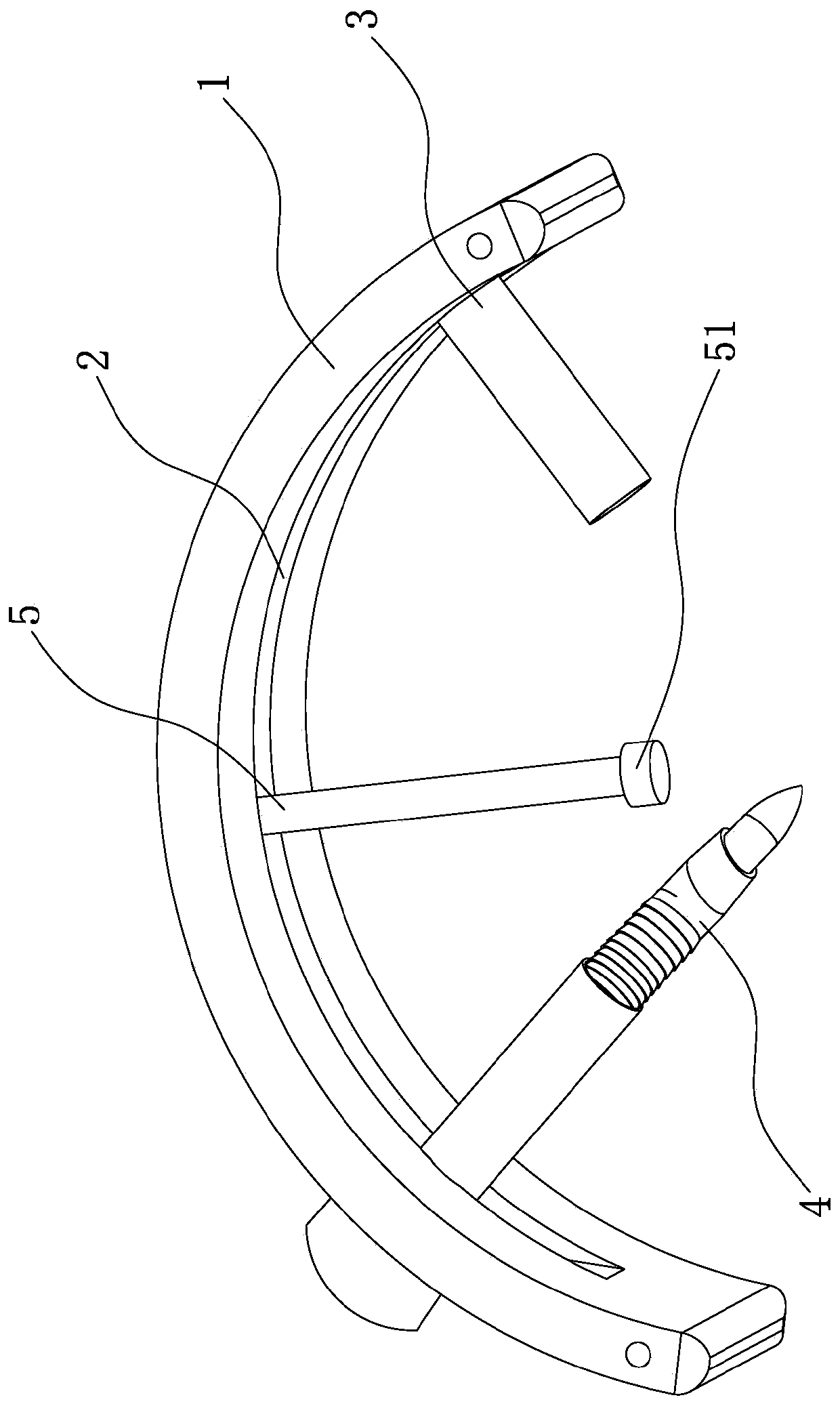
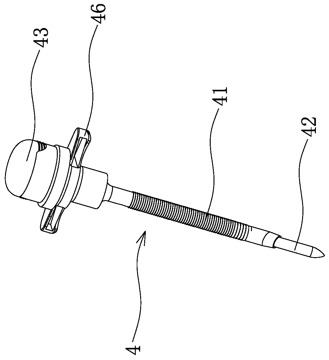
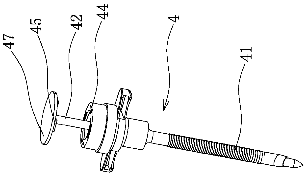
[0034] This embodiment provides a spine bullseye positioning channel forming device, such as figure 1 As shown, it includes an arc-shaped support 1 connected to a universal mechanical arm (not shown in the figure), wherein the universal mechanical arm can be a universal mechanical arm used in the prior art, for example, the application number is For the universal manipulator used in the utility model patent of "201520253482.1" or the utility model patent with the application number of "201820833872.X", the method of connecting the arc support 1 and the universal manipulator can be by opening in the arc support 1 The fixed connection hole on the side surface to realize the connection and fixation. The arc-shaped bracket 1 has an arc-shaped sliding groove 2 that penetrates the inner surface and the outer surface of the arc-shaped bracket 1. The arc of the arc-shaped sliding groove 2 is smaller than that of the arc-shaped bracket 1. In this way, there are blocking devices at both e...
Embodiment 2
[0045] This embodiment provides a method for forming a spine bullseye positioning channel, which combines Figure 1-6 As shown, including the following steps:
[0046] Step 1: Make the patient prone and disinfect the skin of the patient's operation area;
[0047] Step 2: Use X-ray fluoroscopy to determine the spine bull's-eye point O, and mark the back center projection of the spine bull's-eye O point on the body surface according to the spine bullseye O point, and record it as the body surface projection M point;
[0048] Step 3: Measure the distance between the spine bull's-eye point O and the body surface projection M point as d cm;
[0049] Step 4: Mark the puncture route on the patient's body surface, and slide the bullseye reference rod 5 so that the bullseye reference rod 5 extends out of the arc-shaped sliding groove 2 with a length of 18-d cm;
[0050] Step 5: Attach the bullseye reference rod 5 to point M of the body surface projection, and then use the universal mechanical a...
Embodiment 3
[0053] This embodiment provides a method for forming a spine bullseye positioning channel, which combines Figure 1-6 As shown, including the following steps:
[0054] Step 1: Make the patient prone and disinfect the skin of the patient's operation area;
[0055] Step 2: Use X-ray fluoroscopy to determine the spine bull's-eye point O, and mark the back center projection of the spine bull's-eye O point on the body surface according to the spine bullseye O point, and record it as the body surface projection M point;
[0056] Step 3: Measure the distance between the spine bull's-eye point O and the body surface projection M point as d cm;
[0057] Step 4: Mark the puncture route on the patient's body surface, and slide the bullseye reference rod 5 so that the bullseye reference rod 5 extends out of the arc-shaped sliding groove 2 with a length of 18-d cm;
[0058] Step 5: Fit the enlarged part 51 at the end of the bullseye reference rod 5 to the point M of the body surface projection, and...
PUM
 Abstract
Description
Claims
Application Information
 - R&D
- Intellectual Property
- Life Sciences
- Materials
- Tech Scout
- Unparalleled Data Quality
- Higher Quality Content
- 60% Fewer Hallucinations
Browse by: Latest US Patents, China's latest patents, Technical Efficacy Thesaurus, Application Domain, Technology Topic, Popular Technical Reports.
© 2025 PatSnap. All rights reserved.Legal|Privacy policy|Modern Slavery Act Transparency Statement|Sitemap|About US| Contact US: help@patsnap.com


