Floating connector

A technology of floating connectors and auxiliary connections, which is applied in the field of honing processing, can solve problems such as poor tool rotation stability, achieve high processing accuracy, improve processing accuracy, and optimize processing effects

Pending Publication Date: 2019-08-16
安徽多邦珩磨技术有限公司
View PDF1 Cites 4 Cited by
  • Summary
  • Abstract
  • Description
  • Claims
  • Application Information

AI Technical Summary

Problems solved by technology

[0006] Aiming at the problem in the prior art that the tool connector uses a universal joint structure to realize floating, which leads to poor rotation stability of the tool, the present invention provides a floating connector, which uses a cross block to horizontally slide and cooperate with the main connector and the secondary connector instead of the traditional universal joint. The knuckle structure enables the tool to float more smoothly in the horizontal direction, and the machining accuracy is higher; and it will not produce radial swing, so that the hole will not be processed into a trumpet shape; in addition, because the tool does not swing when it rotates, the The centrifugal force caused by the spindle is small and will not affect the accuracy of the machine tool spindle

Method used


Image

  • Floating connector
  • Floating connector
  • Floating connector

Examples


Embodiment 1

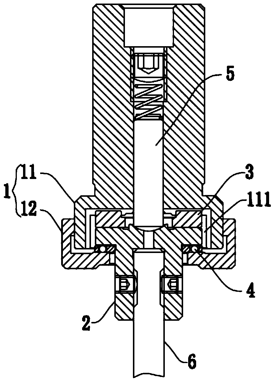
[0052] A floating connector such as figure 1 and Figure 14 As shown, it includes a connecting body assembly 1 and a secondary connecting body 2. The connecting body assembly 1 includes a main connecting body 11 and a lower cover 12; the head of the secondary connecting body 2 is accommodated in the lower end of the main connecting body 11. Inside the floating chamber 111; the lower cover 12 is sleeved outside the secondary connecting body 2, and is detachably connected to the lower end of the main connecting body 11; the floating chamber 111 is also provided with a cross block 3, the The intersection block 3 is slidably connected between the bottom of the floating chamber 111 and the top of the secondary connecting body 2, between the secondary connecting body 2 and the crossing block 3, and between the crossing block 3 and the main connecting body Relative sliding in the horizontal direction can occur between 11; between the secondary connecting body 2 and the cross block 3...

Embodiment 2

[0059] The basic structure of the floating connector of this embodiment is the same as that of Embodiment 1. The difference and improvement lies in that, after the cooperation between the top positioning boss 31 and the bottom positioning groove 112, a space is reserved for the cross Block 3 and the secondary connecting body 2 float up and down the clearance allowance.

[0060] By setting the gap margin, the auxiliary connecting body 2 and the cross block 3 have a floating space for floating up and down, so that the tool has the ability to float up and down, so as to compensate for the thermal deformation of the machine tool, the installation of the workpiece, etc. in the vertical direction. error, optimize the processing effect, and improve the processing accuracy.

Embodiment 3

[0062] A kind of floating connector of this embodiment, the basic structure is the same as embodiment 1 and 2, the differences and improvements are as follows: figure 1 and Figure 14 As shown, it also includes a floating centering assembly 5 arranged in the central hole 113 of the main connecting body 11, the floating centering assembly 5 includes a centering pin 51 and a spring 52, and the lower end of the centering pin 51 passes through Pass through the middle of the intersection block 3 and push into the centering groove 22 at the top center of the auxiliary connecting body 2; the lower end of the spring 52 is sleeved on the upper end of the centering pin 51, and the spring 52 is under compression state. The expansion and contraction of the spring 52 makes the centering pin 51 have a floating displacement in the vertical direction. In this embodiment, the central hole 113 is coaxial with the main connecting body 11 and has a sealed upper end, and the upper end of the spr...


PUM


Abstract

The invention discloses a floating connector, and belongs to the technical field of honing machining. The floating connector comprises a connection body assembly and an auxiliary connection body, wherein the connection body assembly comprises a main connection body and a lower sealing cover; the head part of the auxiliary connection body is accommodated in a floating cavity in the lower end of themain connection body; the lower sealing cover sleeves outside the auxiliary connection body, and is detachably connected with the lower end of the main connection body; a cross block is further arranged in the floating cavity, and slidably connected between the bottom of the floating cavity and the top of the auxiliary connection body; and the auxiliary connection body and the cross block form clearance fit with the inner wall of the floating cavity, and the lower sealing cover forms clearance fit with the outer wall of the auxiliary connection body. According to the floating connector, a structure that the cross block forms horizontal slide fit with the main connection body and the auxiliary connection body is used for replacing a traditional universal joint, so that a tool is enabled tomuch stably float in the horizontal direction, higher honing machining accuracy is achieved, and an orifice is not liable to be machined to be in the shape of a horn; and in addition, due to a centering design during the rotation of the tool, the tool is not liable to swing, accurate entrance into the orifice, of the tool, is achieved, and damage to the orifice is avoided.

Description

technical field [0001] The invention relates to the technical field of honing processing, in particular to a floating connector. Background technique [0002] The honing process (including honing reaming and reaming honing process) is a processing technology for superfinishing the surface of the inner hole of the workpiece with a honing tool. During honing, the workpiece is installed on the honing machine table or in a special fixture, and the honing tool is inserted In the rough-machined bottom hole, the honing tool is driven by the spindle of the machine tool to rotate and reciprocate in the axial direction. The honing rod on the honing tool contacts the wall of the hole to be machined with a certain pressure, and a very thin layer of metal can be cut off. Therefore, the bad shape of the inner hole is cut off, and the machining accuracy of the hole is improved. [0003] The commonly used honing process is usually floating honing. Floating honing includes two floating meth...

Claims


Application Information

Patent Timeline
Patent Type & Authority Applications(China)
IPC IPC(8): B24B33/10B24B33/02
CPCB24B33/02B24B33/10
Inventor 吴学应吴本红
Owner 安徽多邦珩磨技术有限公司
Why Eureka
Try Eureka