A Die-cutting Machine for Insulating Materials Convenient for Buffering and Limiting

An insulating material, die-cutting machine technology, applied in mechanical equipment, vibration suppression adjustment, metal processing, etc., can solve the problems of different shock absorption effect, impact buffer effect, etc., to achieve simple installation, good limit effect, and stable recovery process Effect

Active Publication Date: 2021-06-15
SUZHOU INDAL PARK JIUTAI PRECISION ELECTRONICS
View PDF9 Cites 0 Cited by
  • Summary
  • Abstract
  • Description
  • Claims
  • Application Information

AI Technical Summary

Problems solved by technology

[0003] When die-cutting insulating materials, such as aluminum foil, copper foil, PVC, PET, kraft paper, etc., it needs to be fixed for subsequent processing. The general fixing method is to press the material to be processed by bolts or pressure plates. Not only need to manually adjust the size of the pressure, but also need frequent maintenance to prevent the loosening of the bolts or the aging of the spring during the processing of the material caused by the phenomenon of not being firmly fixed. Shock treatment to prevent the machine from being damaged by the force when the mold collides. The general shock-absorbing and buffering device is a cushion or spring, but the shock-absorbing effect of the cushion is different in high temperature or cold weather, which will affect the cushioning effect. As the main buffer means, the spring needs to consider the problem of reciprocating motion during the spring return process. Therefore, we propose a die-cutting machine for insulating materials that is convenient for buffering and limiting.

Method used


Image

  • A Die-cutting Machine for Insulating Materials Convenient for Buffering and Limiting
  • A Die-cutting Machine for Insulating Materials Convenient for Buffering and Limiting
  • A Die-cutting Machine for Insulating Materials Convenient for Buffering and Limiting

Examples


Embodiment Construction

[0025] The following will clearly and completely describe the technical solutions in the embodiments of the present invention with reference to the accompanying drawings in the embodiments of the present invention. Obviously, the described embodiments are only some, not all, embodiments of the present invention. Based on the embodiments of the present invention, all other embodiments obtained by persons of ordinary skill in the art without making creative efforts belong to the protection scope of the present invention.

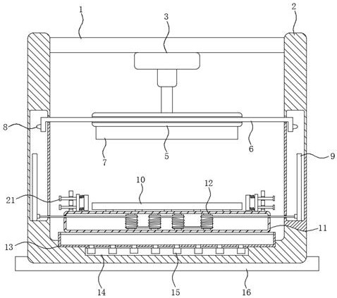
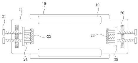
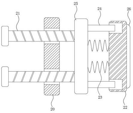
[0026] refer to Figure 1-6 , a die-cutting machine for insulating materials that is convenient for buffering and positioning, including a cross bar 1, a U-shaped frame 2, a working box 11 and a pressing block 10, a die-cutting mechanism is arranged on the cross bar 1, and a U-shaped frame 2 is provided with The adjustment mechanism, the die-cutting mechanism includes a cylinder 3 fixedly installed in the middle of the cross bar 1, a mounting plate 5 is welded...


PUM


Abstract

The invention discloses a die-cutting machine for insulating materials which is convenient for buffering and positioning. It includes a cross bar, a U-shaped frame and a working box. The cross bar is provided with a die-cutting mechanism, and the U-shaped frame is provided with an adjustment mechanism. and a buffer mechanism, the die-cutting mechanism includes a cylinder fixedly installed in the middle of the crossbar, a mounting plate is welded on the piston rod of the cylinder, a cutter is fixedly arranged on the bottom wall of the mounting plate, and the inside of the mounting plate Hollow rods are arranged through, and guide blocks are symmetrically arranged at both ends of the hollow rods. The invention has a novel structure, which well solves the problem of position limitation and buffering during the processing of insulating materials by a die-cutting machine, and has a simple structure, which not only lowers the cost, but also achieves a good effect by consuming very little electric energy. , does not require frequent maintenance of the device, and ordinary workers can also complete the installation and calibration work.

Description

technical field [0001] The invention relates to the technical field of die-cutting machines, in particular to a die-cutting machine for insulating materials which is convenient for buffering and limiting. Background technique [0002] The working principle of the die-cutting machine is to use a die-cutting knife, a steel knife, a metal mold, a steel wire (or a template carved from a steel plate), and apply a certain pressure through the embossing plate to roll and cut the printed matter or cardboard into a certain shape. There are many kinds of cutting techniques. Cutting the entire printed matter into a single graphic product is called die-cutting. Using steel wire to press marks on the printed matter or leaving bent groove marks is called indentation; if two templates of Yin and Yang are used , by heating the mold to a certain temperature, hot stamping a pattern or font with a three-dimensional effect on the surface of the printed product is called hot stamping, and using ...

Claims


Application Information

Patent Timeline
Patent Type & Authority Patents(China)
IPC IPC(8): B26F1/40B26D7/02B26D7/22F16F15/023F16F15/04F16F15/02
CPCB26D7/025B26D7/22B26F1/40F16F15/022F16F15/023F16F15/04
Inventor 韩士超
Owner SUZHOU INDAL PARK JIUTAI PRECISION ELECTRONICS
Why Eureka
Try Eureka