Ceramic rotary slurry spraying forming method

A technology of spraying grouting and ceramics, which is applied in ceramic molding machines, auxiliary molding equipment, supply devices, etc., and can solve problems such as increasing grouting time and amount of slurry, nozzle height cannot be adjusted, and pinholes on the surface of the green body, etc., to avoid Possibility of pinholes, ease of automatic control, effect of improving efficiency

Active Publication Date: 2019-08-16
福建省德化县豪鹏机械有限公司
View PDF5 Cites 4 Cited by
  • Summary
  • Abstract
  • Description
  • Claims
  • Application Information

AI Technical Summary

Problems solved by technology

The patent number is CN201810256090.9, which proposes a ceramic spray molding method, which is also to inject the slurry into the mold of the ceramic product to obtain the green body, but when spraying, the nozzle can neither adjust the height nor rotate the spr

Method used


Image

  • Ceramic rotary slurry spraying forming method
  • Ceramic rotary slurry spraying forming method
  • Ceramic rotary slurry spraying forming method

Examples


Embodiment Construction

[0032] The present invention will be further described below in conjunction with the accompanying drawings and specific embodiments.

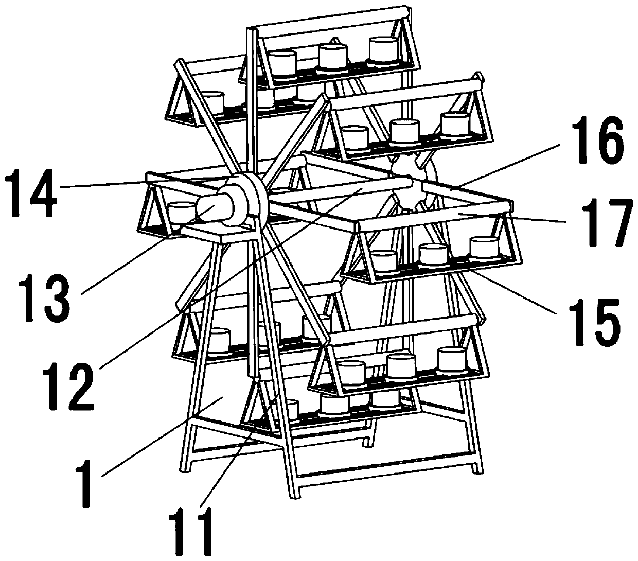
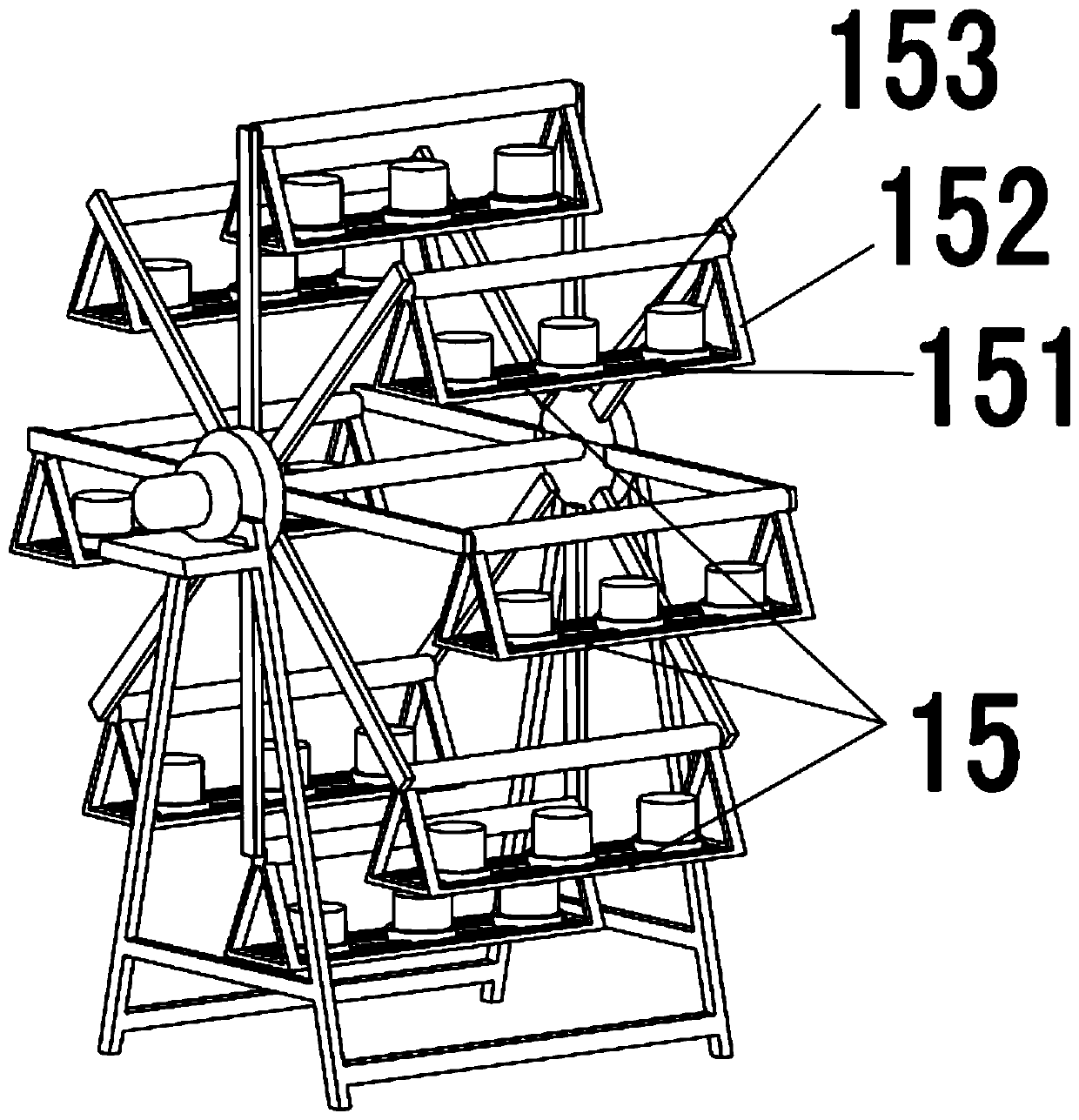
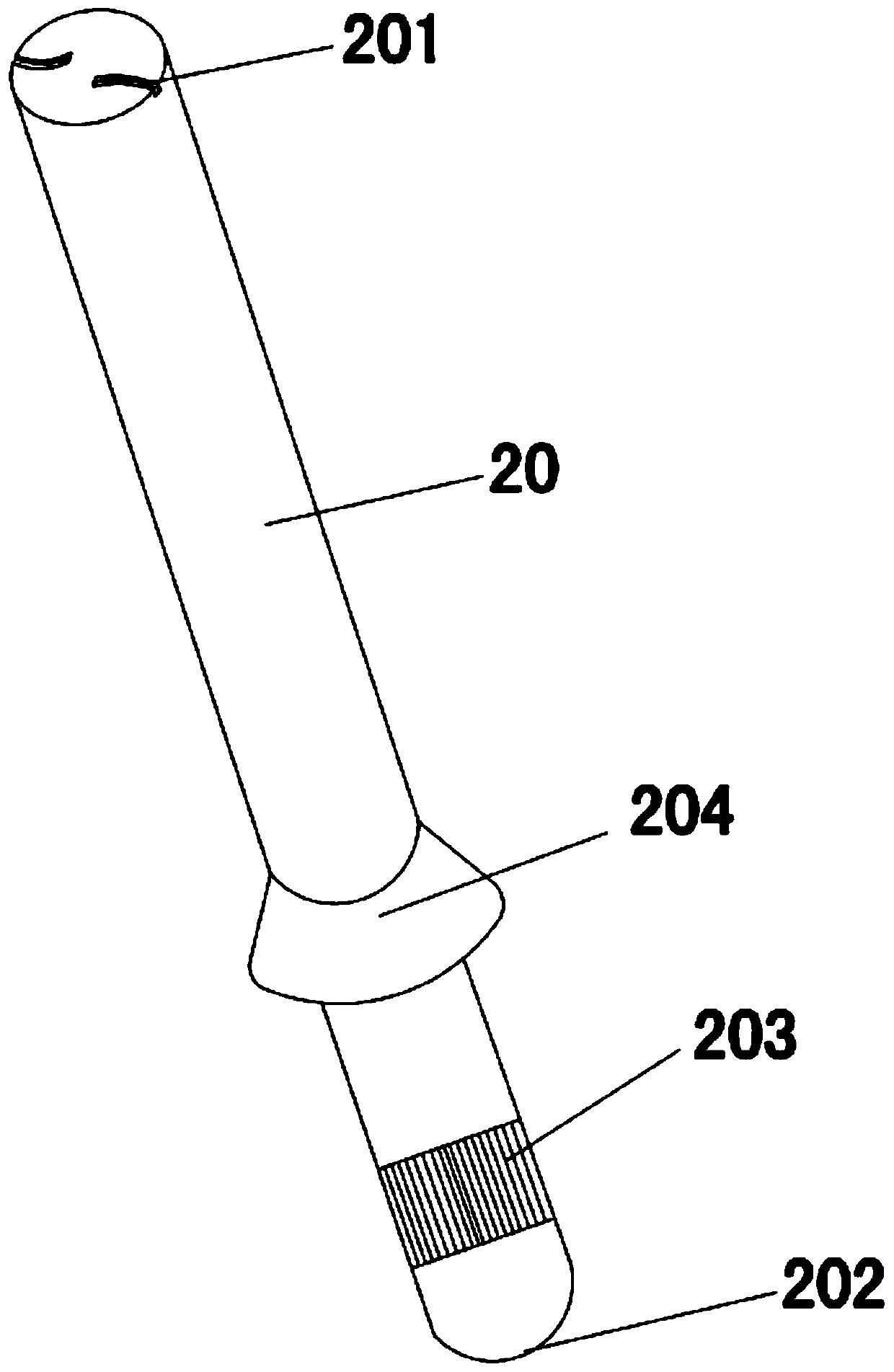
[0033] like Figure 1 to Figure 6 As shown, a method for ceramic rotary spray molding comprises the following steps: (1) mold distribution, the mold that needs to be processed is arranged on the rotary mold transport device 1; (2) mold transport, and the rotary transport mold is operated Die device 1, the mold that needs to be processed is transported to the spraying station; (3) spraying, after the mold is transported to the spraying station, stop the operation of the rotary mold transporting device 1, and extend the nozzle 20 below the station to In the mould, the nozzle 20 rotatably sprays the slurry evenly on the inner wall of the mould, forming a green body; (4) transporting the mold, operating the rotary mold transporting device 1, and transporting the green body to the embryo taking station; (5) ) to take the embryo, after the green bod...


PUM


Abstract

The invention discloses a ceramic rotary slurry spraying forming method. The ceramic rotary slurry spraying forming method is characterized by comprising the following steps that (1) mold arrangementis conducted, specifically, molds needing to be machined are arranged on a rotary mold conveying device; (2) mold transporting is conducted specifically, the molds needing to be machined are transported to slurry spraying stations; (3) slurry spraying is conducted, specifically, after the molds are transported to the slurry spraying stations, nozzles located below the stations are made to stretchinto the molds through a lifting device, the nozzles rotatably spray the slurry onto the inner walls of the molds uniformly, and blank bodies are formed; (4) mold blank transporting is conducted, specifically, the blank bodies are transported to blank taking stations; and (5) blank taking is conducted, specifically, the bank bodies are taken down after being transported to the blank taking stations. According to the ceramic forming method, through the mode that the nozzles spray the slurry rotationally, the slurry can be sprayed onto the interiors of the molds more uniformly, the probability that pores occur to the blank bodies due to traditional slurry injection can be reduced, and the phenomenon that the slurry is not sprayed uniformly is decreased.

Description

technical field [0001] The invention relates to the field of ceramic production, in particular to a ceramic rotary spray molding method. Background technique [0002] At present, most of the ceramic molding adopts grouting molding. Because grouting molding can prepare complex, irregular, thin-walled, large-volume and non-strictly sized utensils. For the spray molding method, the conventional method is to inject the slurry into the mold of the ceramic product, so as to obtain the green body attached to the mold. The patent number is CN201810256090.9, which proposes a ceramic spray molding method, which is also to inject the slurry into the mold of the ceramic product to obtain the green body, but when spraying, the nozzle can neither adjust the height nor rotate the spray, the nozzle can only Injecting the slurry from the grouting port of the mold will cause uneven grouting and pinholes on the surface of the green body, increase the grouting time and the amount of slurry, s...

Claims


Application Information

Patent Timeline
IPC IPC(8): B28B13/02B28B17/00
CPCB28B13/02B28B17/00
Inventor 许光权许文豪
Owner 福建省德化县豪鹏机械有限公司
Why Eureka
Try Eureka