Electric heating die

A technology of electric heating and electric heating device, which is applied to household appliances, other household appliances, household components, etc., can solve the problems of affecting the molding quality, difficult processing, complex flow channel structure, etc.

Pending Publication Date: 2019-08-16
GUANGZHOU TECH LONG PACKAGING MACHINERY CO LTD
View PDF1 Cites 1 Cited by
  • Summary
  • Abstract
  • Description
  • Claims
  • Application Information

AI Technical Summary

Problems solved by technology

At present, there are two types of electric heating molds used in the industry: one is to heat the cavity wall of the mold through a preheating fluid (such as water or oil). Since a large heat exchange is required between the cavity wall and the container, it is More preheating fluid is required, and the reserve of preheating fluid is large. Secondly, since the preheating fluid needs to flow to transfer heat, it is necessary to set up a flow channel in the mold. The structure of the flow channel is complicated, which increases the difficulty of making the mold and manufacturing cost; the other is to heat the mold cavity wall through resistors, as shown in European patent EP1753597, its resistors are arranged at the interface between the mold shell and the bottom mold, when heating, due to the heat volatile from bottom to top The heating effect at the bottom of the container is not good, which affects the molding quality. Secondly, the resistor is in the shape of a coil. Setting the resistor on the bottom mold requires complex processing of the bottom mold, which is difficult and expensive.

Method used


Image

  • Electric heating die
  • Electric heating die
  • Electric heating die

Examples


Embodiment Construction

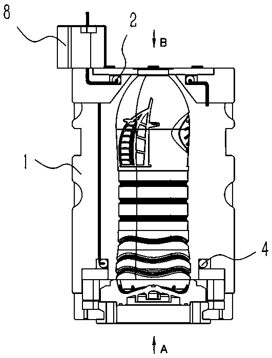
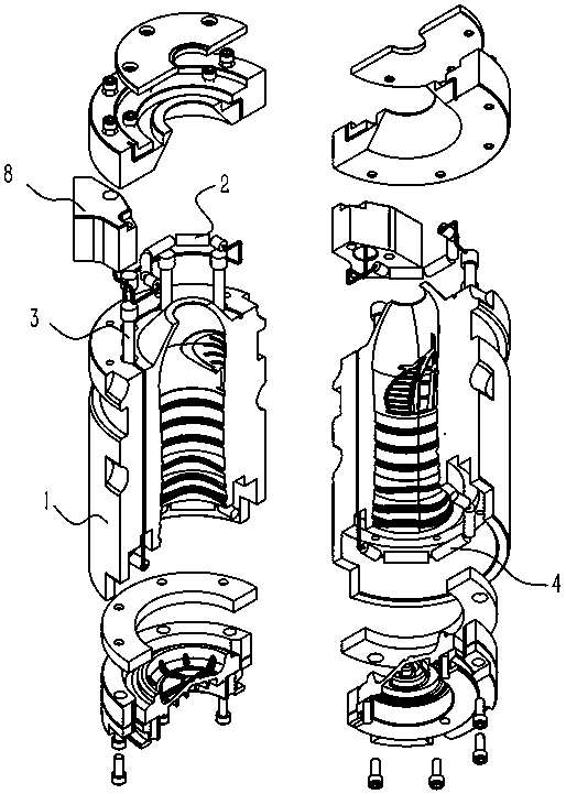
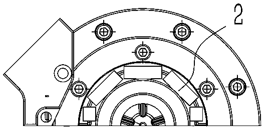
[0013] An electric heating mold, such as Figure 1 to Figure 8 As shown, it includes the mold shell 1 and the electric heating device in the mold shell 1. The electric heating device includes the upper ring heating resistance element group 2 for heating around the bottle neck, and the middle ring in-line heating element group for heating around the bottle body. The columnar heating resistance element group 3 and the lower annular heating resistance element group 4 for heating around the bottom of the bottle.

[0014] The mold shell includes a left mold shell 1 and a right mold shell 2; the upper annular heating resistance element group 2 includes a left semi-annular upper heating resistance element group 3 and a right semi-annular upper heating resistance element group, which are respectively arranged on On the left mold shell and the right mold shell; the middle annular in-line cylindrical heating resistance element group 3 includes a left semi-annular middle in-line cylindri...


PUM


Abstract

An electric heating die comprises a die shell and an electric heating device in the die shell. The electric heating device comprises an upper-layer annular heating resistor element set surrounding a bottleneck for heating, a middle annular straight inserting columnar heating resistor element set surrounding a bottle body for heating, and a lower-layer annular heating resistor element set surrounding a bottle bottom for heating. The electric heating die is good in heating effect, low in machining cost and simple in structure.

Description

technical field [0001] The invention relates to the field of bottle blowing manufacture, in particular to a bottle blowing mold with an electric heating device. Background technique [0002] The preform needs to be put into an electric heating mold and blown into a container bottle. During the blowing process, it needs to be heated so that the preform can be better stretched to form a container bottle. At present, there are two types of electric heating molds used in the industry: one is to heat the cavity wall of the mold through a preheating fluid (such as water or oil). Since a large heat exchange is required between the cavity wall and the container, it is More preheating fluid is required, and the reserve of preheating fluid is large. Secondly, since the preheating fluid needs to flow to transfer heat, it is necessary to set up a flow channel in the mold. The structure of the flow channel is complicated, which increases the difficulty of making the mold and manufacturi...

Claims


Application Information

Patent Timeline
Patent Type & Authority Applications(China)
IPC IPC(8): B29C49/48B29C49/64
CPCB29C49/4823B29C2049/4838B29L2031/7158B29C2049/4846B29C2049/4889B29C49/06B29C2949/0715
Inventor 邓文洲黄孝林
Owner GUANGZHOU TECH LONG PACKAGING MACHINERY CO LTD
Why Eureka
Try Eureka