Unlock instant, AI-driven research and patent intelligence for your innovation.
Airship landing gear
What is Al technical title?
Al technical title is built by PatSnap Al team. It summarizes the technical point description of the patent document.
A landing gear and airship technology, applied in the field of airship landing gear, can solve the problems of difficult processing, heavy weight, complex structure of airship landing gear, etc., and achieve the effect of flexible installation, light weight and simple structure
Active Publication Date: 2019-08-16
CHINA ELECTRONIC TECH GRP CORP NO 38 RES INST
View PDF7 Cites 2 Cited by
Summary
Abstract
Description
Claims
Application Information
AI Technical Summary
This helps you quickly interpret patents by identifying the three key elements:
Problems solved by technology
Method used
Benefits of technology
Problems solved by technology
[0003] The technical problem to be solved by the present invention is: in the prior art, the airship landing gear has complex structure, heavy weight and difficult processing
Method used
Image
Click on the blue label to locate the original text in one second.
Reading with bidirectional positioning of images and text.
Examples
Embodiment 1
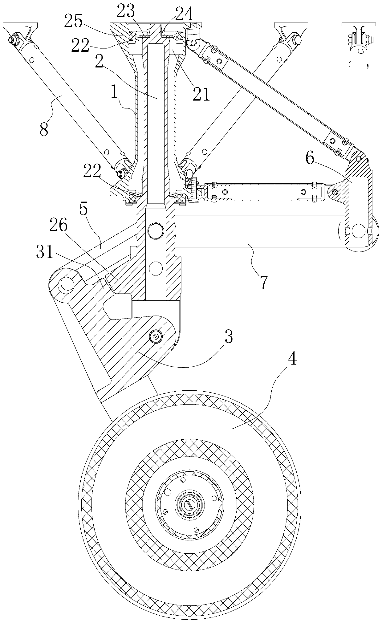
[0058] like figure 1 Shown, a kind of airship undercarriage comprises sleeve 1, rotating mandrel 2, wheel fork 3, wheel 4, first elastic body 5, centering fixing part 6, second elastic body 7, pull rod 8, for convenience For understanding and description, the direction of the airship is on the left.
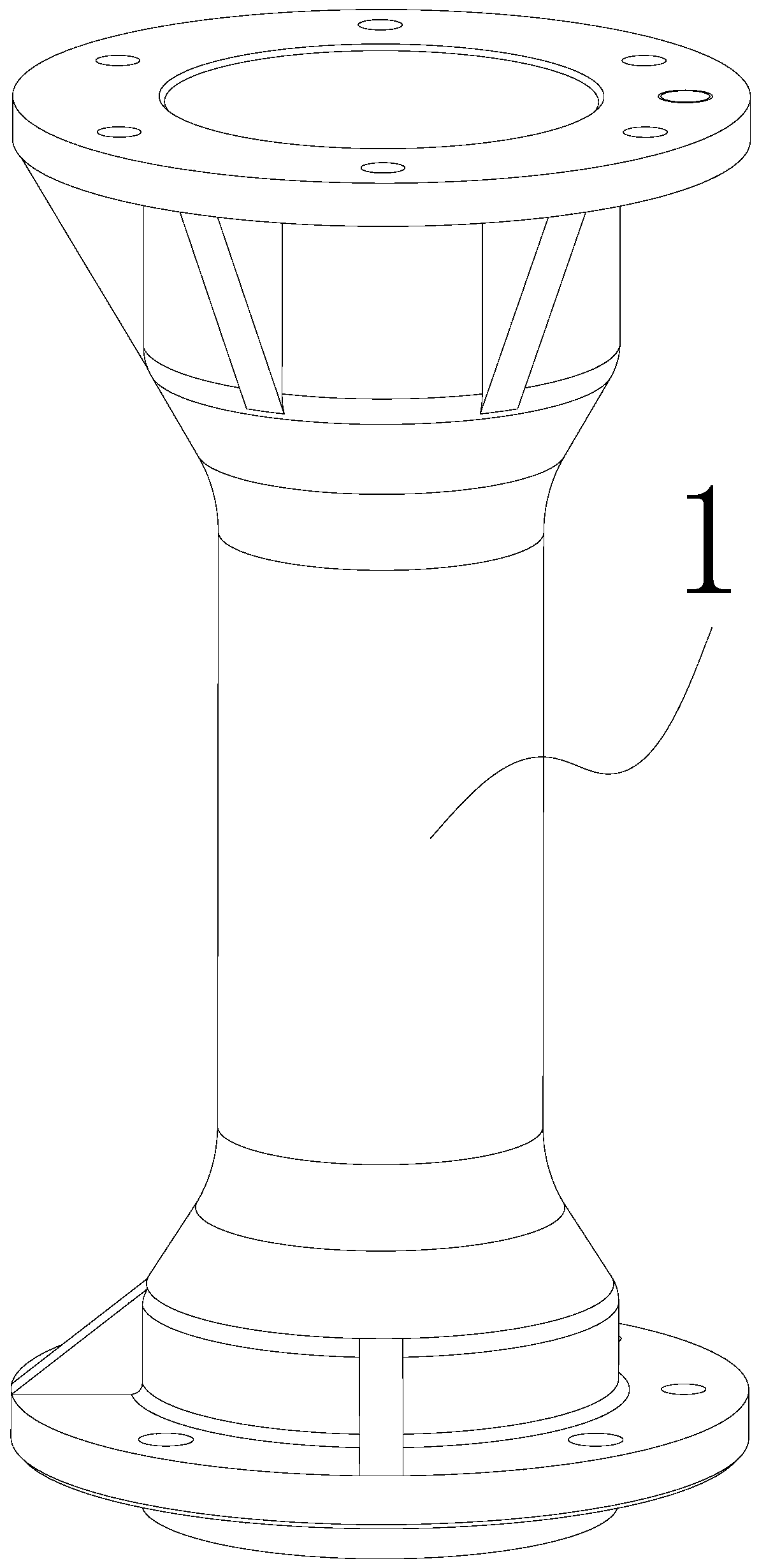
[0059] to combine figure 1 , 2 , the sleeve 1 is a hollow cylindrical part, the upper and lower ends of the sleeve 1 are provided with flanges, and the inner two ends of the sleeve 1 are provided with bearing steps, and the sleeve 1 is vertically arranged on the airship body Bottom, the upper end of the sleeve 1 is connected to the bottom of the airship body by bolts, and a tie rod 8 is arranged between the lower end of the sleeve 1 and the bottom of the airship body. There are four pull rods 8, and the four tie rods 8 are evenly distributed on the sleeve around 1.
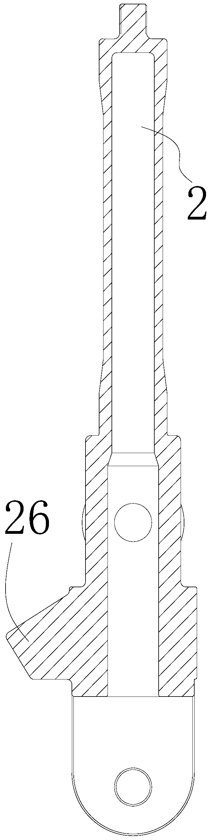
[0060] to combine figure 1 , 3 , 4. A rotating mandrel 2 is rotatably installed in the sleeve 1. The rotatin...
Embodiment 2
[0075] The difference between this embodiment and Embodiment 1 is:
[0076] Both the first elastic body 5 and the second elastic body 7 are extension springs, two machine wheels 4 are provided, the axes of the two machine wheels 4 are located on the same straight line, and the two are arranged side by side.
[0077] working principle:
[0078] In the airship landing gear of the present invention, when the airship lands, the wheel 4 contacts the ground, and the wheel 4 generates an upward supporting reaction force. amplitude swing, the first elastic body 5 will produce a certain deformation to resist the swing of the wheel fork 3, and then play a buffering role, while being able to withstand, absorb and consume the impact and bump energy of the airship when it is landing and gliding. In addition, Under the action of the second elastic body 7, when the moments generated by the second elastic body 7 on both sides of the rotating mandrel 2 are equal in size and opposite in direct...
PUM
Abstract
The invention discloses an airship landing gear which comprises a sleeve vertically arranged at the bottom of an airship body, wherein a rotating mandrel is rotatably installed in the sleeve, a wheelfork is hinged to the lower end of the rotating mandrel, and an articulated shaft is in the horizontal direction; an airship wheel is arranged on the wheel fork, the axis of the airship wheel is parallel to the hinge shaft of the rotating mandrel and the wheel fork, and the axis of the airship wheel is positioned on one side of the articulated shaft of the rotating mandrel and the wheel fork; a first elastic body is arranged between the wheel fork and the rotating mandrel, the connection point of the first elastic body and the rotating mandrel, the connection point of the first elastic body and the wheel fork, and the articulated shaft of the rotating mandrel and the wheel fork form a triangle; the airship landing gear further comprises a centering fixing piece, at least one second elasticbody is arranged between the two sides of the rotating mandrel and the centering fixing piece correspondingly, and when moments generated by the second elastic bodies on the two sides of the rotatingmandrel are equal in magnitude and opposite in direction, the axis of the airship wheel is perpendicular to the advancing direction of an airship. The airship landing gear has the advantages of simple structure, light weight and simple machining.
Description
technical field [0001] The invention relates to the field of airships, in particular to an airship landing gear. Background technique [0002] With the rapid development of economy and technology, my country's high-altitude airship has made continuous progress. Airship is a kind of aerostat, which is an aircraft that uses gas lighter than air to provide lift. The landing gear of the airship is a kind of landing device, which is equivalent to the ground buffer. The structure of the landing gear of the airship is unique, rich and diverse, and the common ones are rocker type and pillar type. , three-point type, etc. Different structural layouts and designs have different effects. In the design of landing gear devices, it is necessary to select the appropriate structural form, layout form and buffer device form in combination with the characteristics of the design device. The task of the landing gear is mainly to bear, absorb and consume the impact and bump energy of the airshi...
Claims
Application Information
Patent Timeline
Application Date:The date an application was filed.
Publication Date:The date a patent or application was officially published.
First Publication Date:The earliest publication date of a patent with the same application number.
Issue Date:Publication date of the patent grant document.
PCT Entry Date:The Entry date of PCT National Phase.
Estimated Expiry Date:The statutory expiry date of a patent right according to the Patent Law, and it is the longest term of protection that the patent right can achieve without the termination of the patent right due to other reasons(Term extension factor has been taken into account ).
Invalid Date:Actual expiry date is based on effective date or publication date of legal transaction data of invalid patent.
Patent Type & Authority Applications(China)
IPC IPC(8): B64B1/00
CPCB64B1/005
Inventor 陶海峰李浩韦春海张志富周萌薛松海王平安仝允吴斌杨竣博贺旭东闫修
Owner CHINA ELECTRONIC TECH GRP CORP NO 38 RES INST
