
Reciprocating subsurface flow constructed wetland filled by longitudinal substrates and application of constructed wetland

A constructed wetland, reciprocating technology, applied in the direction of water pollutants, water/sludge/sewage treatment, biological water/sewage treatment, etc., can solve the problems of carbon source consumption, nitrogen removal performance reduction, etc., and achieve enhanced nitrogen removal performance , strong adsorption, simple and easy operation

Pending Publication Date: 2019-08-16
UNIV OF JINAN
View PDF7 Cites 0 Cited by
  • Summary
  • Abstract
  • Description
  • Claims
  • Application Information

AI Technical Summary

Problems solved by technology

The application types of constructed wetlands mainly include single type and composite type. Among them, the types of composite constructed wetlands mainly include horizontal subsurface flow with upward vertical flow, and vertical flow with horizontal subsurface flow. The sewage in the existing operation mode enters in a predetermined order. The retention stratification is obvious, which leads to the reduction of nitrogen removal performance. At the same time, the carbon source in the sewage is continuously consumed during the hydraulic retention time, which further leads to the reduction of nitrogen removal performance.

Method used


Image

  • Reciprocating subsurface flow constructed wetland filled by longitudinal substrates and application of constructed wetland
  • Reciprocating subsurface flow constructed wetland filled by longitudinal substrates and application of constructed wetland
  • Reciprocating subsurface flow constructed wetland filled by longitudinal substrates and application of constructed wetland

Examples


Embodiment Construction

[0035] It should be pointed out that the following detailed description is exemplary and intended to provide further explanation to the present application. Unless defined otherwise, all technical and scientific terms used herein have the same meaning as commonly understood by one of ordinary skill in the art to which this application belongs.

[0036]In order to enable those skilled in the art to understand the technical solution of the present application more clearly, the technical solution of the present application will be described in detail below in conjunction with specific embodiments.

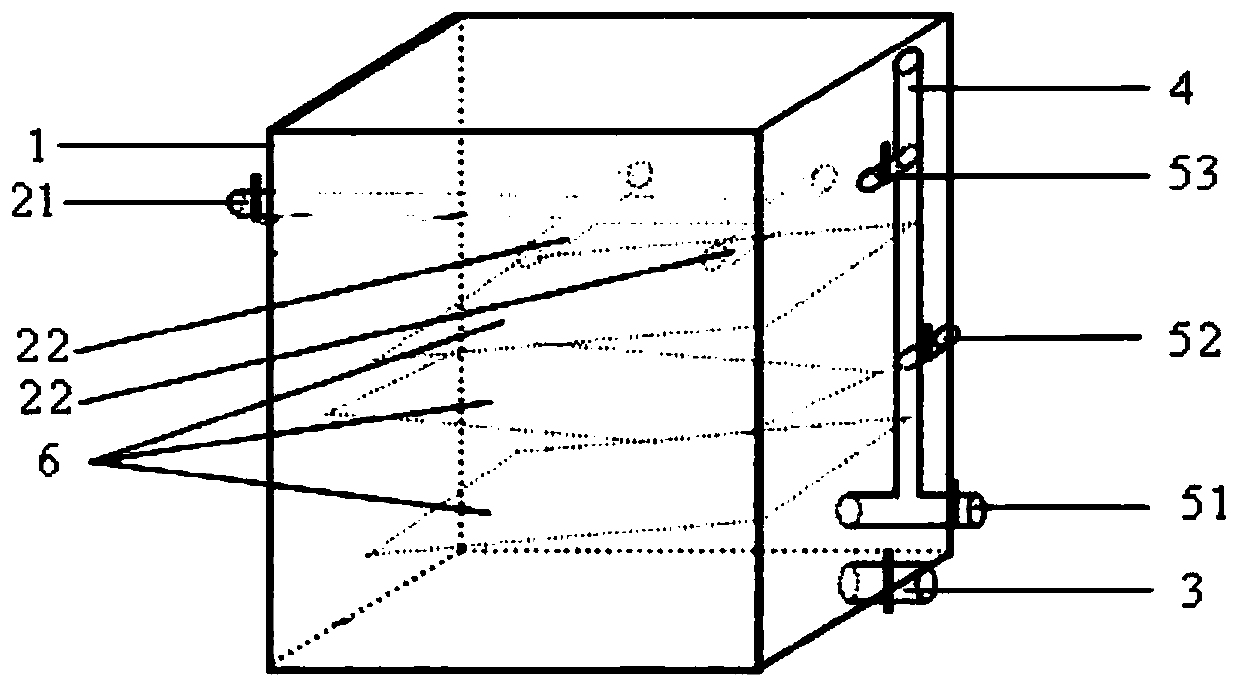
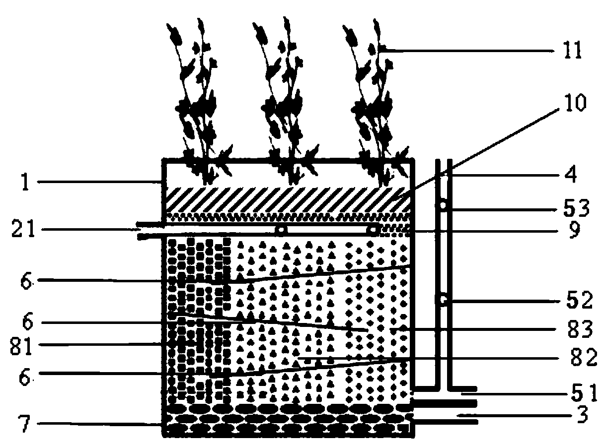
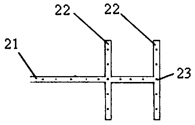
[0037] Such as figure 1 , 2 As shown, a reciprocating subsurface flow artificial wetland filled with vertical matrix includes a pool body 1, which is a trough-shaped structure with an open top. The pool body 1 is a cube made of plexiglass with a thickness of 5 mm and a size of length×width×height=500mm×400mm×550mm, with a volume of 110L. The periphery of the pool body 1 is blackene...


PUM

PropertyMeasurementUnit
Diameteraaaaaaaaaa

Abstract

The invention discloses a reciprocating subsurface flow constructed wetland filled by longitudinal substrates. The constructed wetland comprises a pool body, the pool body has a tank-shaped structurewith an open top, and the interior of the pool body is filled with the substrates; the substrates comprise a base layer, a generation layer, a barrier layer and a planting layer from the bottom to thetop; the generation layer comprises at least two substrates which longitudinally fill the generation layer from the left to the right; a water inlet pipe extending in a horizontal direction is arranged at the upper portion of the pool body, and a water outlet pipe is connected to the bottom of the pool body; and at least one layering partition plate of which one side is inclined downwards is arranged in the generation layer, one higher side of the layering partition plate is in tightly attached to the pool body, and one lower side is spaced from the pool body. The constructed wetland providedby the invention enables sewage to pass through the different substrates in different orders to form a reciprocating water flow, so that the sewage can be uniformly mixed during hydraulic retention,a hydraulic retention layering phenomenon is avoided, and the microbial nitrogen removal performance is enhanced.

Description

technical field [0001] The invention relates to the technical field of constructed wetlands, in particular to a longitudinal matrix-filled reciprocating subsurface flow constructed wetland and its application. Background technique [0002] With the development of society and the improvement of people's living standards, the amount of domestic sewage is increasing day by day, and the phenomenon of random discharge is serious, which not only wastes water resources, but also causes environmental pollution. As a new type of sewage treatment process, constructed wetland has the advantages of simple structure, easy maintenance, low treatment cost, and landscape effect. It plays an important role in sewage treatment and ecological environment protection, and has good promotion value. [0003] Constructed wetlands are mainly composed of three parts: substrate, plants and microorganisms. The matrix mainly plays three roles in the constructed wetland: the attachment surface for micro...

Claims


Application Information

Patent Timeline
IPC IPC(8): C02F3/32C02F101/16
CPCC02F3/32C02F2101/16C02F2101/163Y02W10/10
Inventor 徐晓寒王惠杨宝山王树志来晓双袁英睿李峰
Owner UNIV OF JINAN
Learn More