
Pre-buried support-hanger device and manufacturing and construction mounting methods thereof

An installation method and a technology of support and hanger, which are applied in the direction of supporting machines, mechanical equipment, buildings, etc., can solve the problems of small force bearing surface of expansion screws, affect accurate positioning, increase construction cost, etc., achieve reduced construction strength, accurate positioning, The effect of safety improvement

Pending Publication Date: 2019-08-16
广西建工第五建筑工程集团有限公司
View PDF0 Cites 0 Cited by
  • Summary
  • Abstract
  • Description
  • Claims
  • Application Information

AI Technical Summary

Problems solved by technology

[0003] 1. The force surface of the expansion screw is small, which affects the pulling force;
[0004] 2. It is easy to collide with the steel bar when installing the expansion screw, which affects the precise positioning;
[0005] 3. High labor intensity, time-consuming and labor-intensive, increasing construction cost

Method used


Image

  • Pre-buried support-hanger device and manufacturing and construction mounting methods thereof
  • Pre-buried support-hanger device and manufacturing and construction mounting methods thereof
  • Pre-buried support-hanger device and manufacturing and construction mounting methods thereof

Examples


Embodiment 1

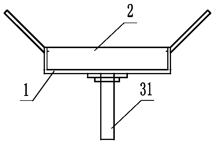
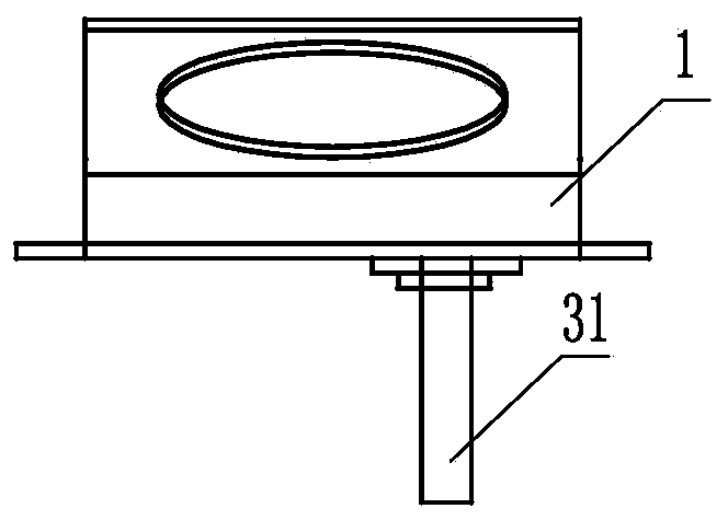
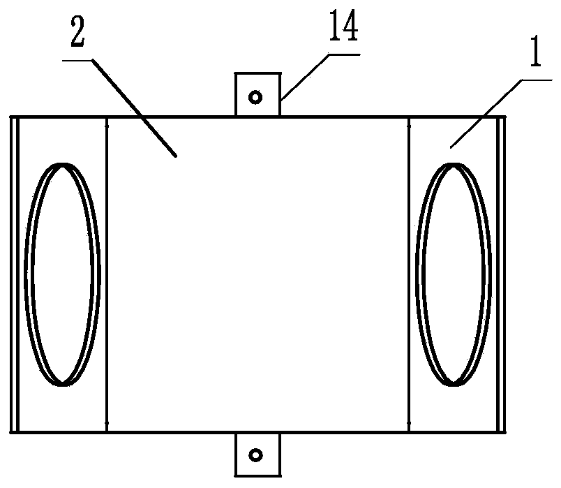
[0063] A pre-embedded support and hanger device, including a support and hanger main body I and a hanger assembly III; the support and hanger main body I includes a U-shaped base 1 and an inverted U-shaped cover groove 2, and the U-shaped base 1 includes a bottom plate 11 and the side vertical sides 12 symmetrically connected to the left and right sides thereof, the tops of the left and right side vertical sides are respectively connected to the extension plate 13, and the angle α formed between the extension plate and the side vertical side is 90-130°;

[0064] The middle part of the base plate 11 is provided with a cross-shaped slot 111, including longitudinal slots and transverse slots with the same slot width, and the front and rear ends of the base plate 11 are connected with lateral connecting plates 14;

[0065] Described inverted U-shaped cover groove comprises cover groove top plate 21 and the cover groove vertical edge 22 that is symmetrically connected in its front a...

Embodiment 2

[0075] A method for manufacturing a pre-embedded support and hanger device, comprising the steps of:

[0076] S11 Make a U-shaped base according to the specifications required by the design;

[0077] Press the rough surface of the thin steel plate as a whole to make a U-shaped base with a rough surface, the bottom plate, the side vertical edge and the extension plate integrated into one;

[0078] S12 Make an inverted U-shaped cover groove according to the specifications required by the design;

[0079] It is integrally pressed with a thin steel plate to make an inverted U-shaped cover trough that is integrated with the cover trough top plate and the vertical side of the cover trough;

[0080] S13 making the main body of the support and hanger;

[0081] S131 buckle the inverted U-shaped cover groove on the bottom plate of the U-shaped base through welding or bonding with an adhesive, so that the inverted U-shaped cover groove, the bottom plate and the vertical sides on both s...

Embodiment 3

[0097] S2 A construction and installation method for a pre-embedded support and hanger device, the steps are:

[0098] S21 When binding the steel bars at the bottom of the floor slab, according to the design requirements, mark the position where the embedded support and hanger device needs to be installed;

[0099] S22 Install the main body of the embedded support and hanger;

[0100] Install the support and hanger main body made in step S13 in the bottom steel bar at the positioning mark, the bottom plate of the support and hanger main body is attached to the flat bottom formwork, and the iron nails are fixed to the bottom formwork through the lateral connecting plate. Repeat this step to install all the support hangers. Hanger body;

[0101] S23 Pouring concrete;

[0102] After the S24 concrete is dry, remove the bottom formwork;

[0103] S25 install the boom assembly;

[0104] S251 Tear off the adhesive film on the bottom plate of the main body of the support and hanger...


PUM


Abstract

The invention provides a pre-buried support-hanger device, which comprises a support-hanger main body and a suspender assembly. The suspender assembly comprises a screw, an upper nut, an upper clamping plate, a lower clamping plate and a screwing nut which are sequentially mounted together; the support-hanger main body comprises a U-shaped base and an inverted-U-shaped cover groove which are formed together in a buckled mode; the vertical edges on the left side and the right side of the U-shaped base are connected with outward-extending plates correspondingly; and a cross-shaped groove hole isformed in the middle of a bottom plate of the U-shaped base, and the suspender assembly is mounted on the lower part of the bottom plate in a clamped mode through the cross-shaped groove hole. The pre-buried support-hanger device can be made of a thin steel plate or high-strength plastic, factory production can be achieved, the structure is simple, tie force between the support-hanger main body and concrete is high, and the application range is wide. The construction mounting method of the pre-buried support-hanger device comprises the steps: when steel bars at the bottom of a floor are bound, the support-hanger main body is pre-buried, the concrete is poured, and after a formwork is dismantled, the suspender assembly is mounted. The mounting method is easy and convenient, high in efficiency and accurate in positioning, a concrete structure does not need to be destroyed, and the labor intensity can be lowered greatly.

Description

technical field [0001] The invention relates to a support and hanger device for building construction and a manufacturing and construction method thereof, in particular to a pre-embedded support and hanger device and a manufacturing, construction and installation method thereof. Background technique [0002] With the rapid development of construction technology, the structural environment is complex and the installation system is diversified, the quality control is particularly critical. The electromechanical installation project is an important factor affecting the quality of the building. The support and hanger installation in the electromechanical installation project is one of its core processes. 1. The existing support and hanger is tied in the later stage by installing expansion screws. The existing problems are: [0003] 1. The force surface of the expansion screw is small, which affects the pulling force; [0004] 2. It is easy to collide with the steel bar when ins...

Claims


Application Information

Patent Timeline
Patent Type & Authority Applications(China)
IPC IPC(8): E04B1/41E04G21/00F16M13/02
CPCE04B1/41E04G21/00F16M13/02
Inventor 赵成陈凌云覃可杰陆征宇彭何新陈祝华
Owner 广西建工第五建筑工程集团有限公司
Learn More